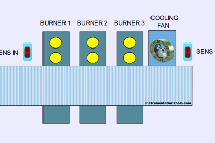
The start-up control for the boilers is enabled via a master thermostat. PLC control is to be used to ensure that 4 gas boilers do not start up simultaneously in the system.
Write PLC program for this application using ladder diagram language.
PLC Ladder Logic for Start-up Control of Boilers

Solution
Each of the four boilers has two power settings. Each power setting is assigned to PLC.
The master thermostat is connected to PLC input. The thermostat is used to set the temperature at which the boiler is to be switched on and off. Say, If the temperature falls below 75°C, the first power setting of boiler 1 is activated for heating.
Five minutes later, power setting 2 of boiler 1 is activated. Provided that the final temperature has not been reached, a further power setting is enabled for reheating at intervals of 5 minutes.
When the final temperature of 85°C is reached, the boilers are switched off in sequence. Starting with power setting 1 and 2 of boiler 1, then after 5 minutes boiler 2, etc.
When the temperature falls, the boilers are activated again, starting with power setting 1.
List of Inputs/Outputs
List of Inputs
- I0.0:-Mater thermostat
List of Outputs
- Q0.1:-Power setting 1-boiler 1
- Q0.2:-Power setting 2-boiler 1
- Q0.3:-Power setting 1-boiler 2
- Q0.4:-Power setting 2-boiler 2
- Q0.5:-Power setting 1-boiler 3
- Q0.6:-Power setting 2-boiler 3
- Q0.7:-Power setting 1-boiler 4
- Q1.0:-Power setting 2-boiler 4
Ladder diagram for start-up control for boilers


Program Description
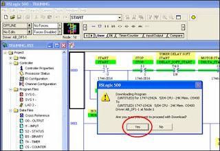
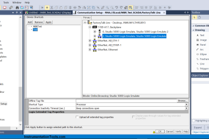
In this program we have used Siemens S7-300 PLC and TIA Portal Software for programming.
Network 1 :-
When thermostat input (I0.0) is activated, power setting 1(Q0.1) for boiler 1 will be ON.
Network2 :-
After 5 minutes interval power setting 2(Q0.2) for boiler 1 will be ON.
Network 3 :-
After 10 minutes interval power setting 1(Q.3) for boiler 2 will be ON.
Network 4 :-
After 15 minutes interval power setting 2(Q.4) for boiler 2 will be ON.
Network 5 :-
After 20 minutes interval power setting 1(Q.5) for boiler 3 will be ON.
Network 6 :-
After 25 minutes interval power setting 2(Q.6) for boiler 3 will be ON.
Network 7 :-
After 30 minutes interval power setting 1(Q.7) for boiler 4 will be ON.
Network 8 :-
After 35 minutes interval power setting 1(Q1.0) for boiler 4 will be ON.
Note:- Above application may be different from actual application. This example is only for explanation purpose only. We can implement this logic in other PLC also. This is the simple boiler power setting sequence control using PLC, we can use this concept in other examples also.
All parameters and graphical representations considered in this example are for explanation purpose only, parameters or representation may be different in actual applications. Also all interlocks are not considered in the application.
Author : Bhavesh
If you liked this article, then please subscribe to our YouTube Channel for PLC and SCADA video tutorials.
You can also follow us on Facebook and Twitter to receive daily updates.
Read Next:


For this logic supposed to be use TON timer.