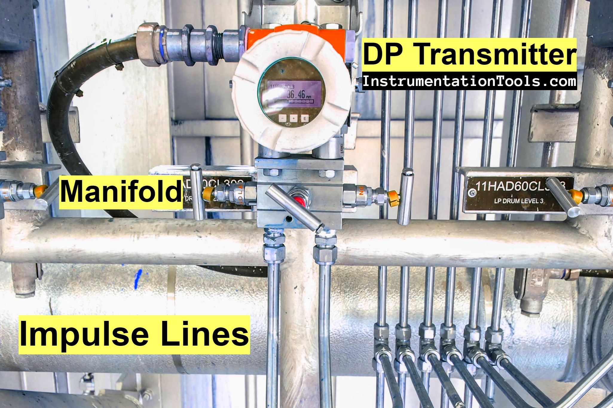
Instrumentation impulse lines are small-bore pipes that are used to connect the process pipeline with the transmitters and instruments.
Impulse lines transfer the process pressure accurately to the transmitter, which then converts this pressure into a proportional signal.
Key Considerations for Impulse Lines
The main key considerations of impulse lines are mentioned below.
Positioning
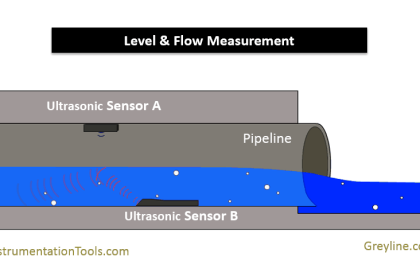
The positioning of impulse lines is crucial for accurate readings. For flow measurements, impulse lines should be connected at the same horizontal level to avoid measurement errors due to the head of fluid in the lines.
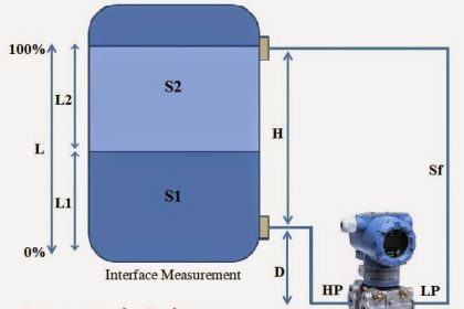
For level measurements, they should be connected at different vertical levels corresponding to the high and low points of the tank.
Installation
Impulse lines should be as short as possible to minimize the potential for error. They should also be installed in a way that avoids trapping gases in liquid lines or liquids in gas lines.
Temperature and Pressure
Impulse lines must be designed to withstand the process temperature and pressure. They should also be insulated if there’s a risk of temperature fluctuation, as this can lead to measurement errors.
Maintenance
Impulse lines should be easy to access for maintenance purposes. They should also include valves for isolation and drains/vents for purging when necessary.
Common Issues with Impulse Lines
The common issues related to the impulse lines are mentioned below.
Blockages
Impulse lines can become blocked due to sediment or frozen process fluid. Regular maintenance and appropriate installation can help prevent this.
Leaks
Leaks can lead to inaccurate pressure readings. Regular inspections can help detect and fix leaks promptly.
Pulsation
Pulsation or pressure surges in the process fluid can cause measurement errors. Dampeners can be used to mitigate this issue.
Material Selection
The material of the impulse lines should be compatible with the process fluid to prevent corrosion or degradation. Stainless steel is commonly used due to its resistance to a wide range of chemicals.
Other materials like copper, PVC, or special alloys may be used depending on the nature of the process fluid.
Sloping of Impulse Lines
The slope of impulse lines is a critical factor in their design. For gas or steam applications, impulse lines should slope upwards from the process connection to the transmitter. This allows any condensate to drain back into the process.
Conversely, for liquid applications, impulse lines should slope downwards from the process connection to the transmitter. This allows any trapped gas to be carried back into the process.
Heat Tracing and Insulation
In some applications, especially where the process fluid can freeze or solidify at low temperatures, impulse lines may need to be heat traced and insulated.
Heat tracing involves running a heated wire along the length of the impulse line to keep it at a constant temperature. Insulation is then added over the heat tracing to maintain the temperature and protect the line.
Equalizing and Venting
Impulse lines often come with equalizing and venting valves. Equalizing valves are used to balance the pressure between the high-pressure and low-pressure sides of the transmitter during calibration or zeroing.
Venting valves, on the other hand, are used to release any trapped air or gas in the lines.
Impulse Line Maintenance
Regular maintenance of impulse lines is crucial to ensure accurate and reliable measurements. This includes periodic cleaning to remove any blockages, checking for leaks, and ensuring that heat tracing and insulation are in good condition.
The performance of the transmitter should be regularly checked and calibrated to ensure it is reading the pressures accurately.
Impulse Line Configurations
There are several configurations of impulse lines that can be used depending on the application:
- Direct Mounting: The transmitter is directly mounted on the process line. This is the simplest configuration and eliminates the need for impulse lines. However, it’s not suitable for all applications, especially when the process fluid is corrosive or at a high temperature.
- Vertical Mounting: The impulse lines run vertically from the process line to the transmitter. This configuration is used when the process fluid is a liquid to allow any trapped gas to be vented back into the process.
- Horizontal Mounting: The impulse lines run horizontally from the process line to the transmitter. This configuration is used when the process fluid is a gas to allow any condensate to drain back into the process.
Impulse Line Problems and Solutions
Some of the problems and solutions of impulse lines are mentioned below.
Blockages
Blockages in impulse lines can occur due to the accumulation of particulates or due to the freezing of the process fluid. This can lead to inaccurate pressure readings.
Solution: Regular maintenance and cleaning of impulse lines can help prevent blockages. In addition, heat tracing can be used to prevent freezing in cold environments.
Leaks
Leaks in impulse lines can lead to a loss of pressure and inaccurate readings.
Solution: Regular inspections can help identify and fix leaks early. Using high-quality fittings and seals can also help prevent leaks.
Thermal Effects
Changes in temperature can cause the fluid in the impulse lines to expand or contract, leading to inaccurate pressure readings.
Solution: Insulating impulse lines can help maintain a consistent temperature and prevent these errors. In addition, impulse lines should be kept as short as possible to minimize the effects of temperature changes.
Time Delays
The time it takes for a pressure change to propagate through the impulse lines can lead to measurement errors, especially in dynamic processes.
Solution: Keeping impulse lines as short as possible can help minimize time delays. In addition, using a higher-pressure fluid in the impulse lines can also help reduce the propagation time.
Pulsation
Pulsation or pressure surges in the process fluid can cause measurement errors.
Solution: Dampeners can be used to reduce pulsation in the process fluid. In addition, the use of a three-valve manifold can allow for the isolation of the transmitter from the process during periods of high pulsation.
Conclusion
Impulse lines play a crucial role in the accurate operation of pressure-based transmitters. Impulse lines can present several challenges, and understanding these challenges and how to mitigate them can help ensure accurate and reliable measurements.
Proper design, installation, and maintenance of these lines are essential for optimal performance.
If you liked this article, then please subscribe to our YouTube Channel for Instrumentation, Electrical, PLC, SCADA, and Industrial Automation video tutorials.
You can also follow us on Facebook and Twitter to receive daily updates.
- Impulse Piping for Field Instruments
- Pressure Transmitters Purge Lines
- Impulse Tubing Leak Test Checks
- Transmitter Heat-traced impulse line
- DP Transmitter Wet Leg Questions


Bi-metallic corrosion is one common problem observed when the impulse lines were laid with the support of structures. Suitable insulating clamps to be provided between the impulse line and the structures to avoid bi-metallic corrosion.
You excluded the mention of Impulse piping used in Steam applications.
Here, the transmitter is always mounted BELOW the lines to allow for the build up of Condensate in the lines.