Inst ToolsInst ToolsInst Tools
  • Courses
  • Automation
    • PLC
    • Control System
    • Safety System
    • Communication
    • Fire & Gas System
  • Instrumentation
    • Design
    • Pressure
    • Temperature
    • Flow
    • Level
    • Vibration
    • Analyzer
    • Control Valve
    • Switch
    • Calibration
    • Erection & Commissioning
  • Interview
    • Instrumentation
    • Electrical
    • Electronics
    • Practical
  • Q&A
    • Instrumentation
    • Control System
    • Electrical
    • Electronics
    • Analog Electronics
    • Digital Electronics
    • Power Electronics
    • Microprocessor
  • Request
Search
  • Books
  • Software
  • Projects
  • Process
  • Tools
  • Basics
  • Formula
  • Power Plant
  • Root Cause Analysis
  • Electrical Basics
  • Animation
  • Standards
  • 4-20 mA Course
  • Siemens PLC Course
Reading: Pilot-operated Safety and Relief Valves
Share
Notification Show More
Font ResizerAa
Inst ToolsInst Tools
Font ResizerAa
  • Courses
  • Design
  • PLC
  • Interview
  • Control System
Search
  • Courses
  • Automation
    • PLC
    • Control System
    • Safety System
    • Communication
    • Fire & Gas System
  • Instrumentation
    • Design
    • Pressure
    • Temperature
    • Flow
    • Level
    • Vibration
    • Analyzer
    • Control Valve
    • Switch
    • Calibration
    • Erection & Commissioning
  • Interview
    • Instrumentation
    • Electrical
    • Electronics
    • Practical
  • Q&A
    • Instrumentation
    • Control System
    • Electrical
    • Electronics
    • Analog Electronics
    • Digital Electronics
    • Power Electronics
    • Microprocessor
  • Request
Follow US
All rights reserved. Reproduction in whole or in part without written permission is prohibited.
Inst Tools > Blog > Control Valves > Pilot-operated Safety and Relief Valves

Pilot-operated Safety and Relief Valves

Last updated: March 28, 2019 4:12 pm
Editorial Staff
Control Valves Safety Instrumented System (SIS)
No Comments
Share
4 Min Read
SHARE

While many safety and relief valves actuate by the direct action of the process fluid forcing against the valve plug mechanism, others are more sophisticated in design, relying on a secondary pressure sensing mechanism to trigger and direct fluid pressure to the main valve assembly to actuate it.

Contents
Pilot-operated Safety and Relief ValvesComparison to non piloted pressure relief valvesAdvantagesDisadvantages

This pressure-sensing mechanism is called a pilot, and usually features a widely-adjustable range to give the overall valve assembly a larger variety of applications.

In a pilot-operated over-pressure-protection valve, the “lift” pressure value is established by a spring adjustment in the pilot mechanism rather than by an adjustment made to the main valve mechanism.

Pilot-operated Safety and Relief Valves

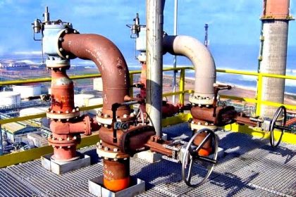
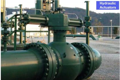
A photograph of a pilot-operated pressure relief valve used on a liquid petroleum pipeline appears here:

Pilot-operated Safety and Relief Valves

This photograph courtesy of the National Transportation Safety Board’s report of the 1999 petroleum pipeline rupture in Bellingham, Washington. Improper setting of this relief valve pilot played a role in the pipeline rupture, the result of which was nearly a quarter-million gallons of gasoline spilling into a creek and subsequently igniting.

One of the lessons to take from this event is the importance of proper instrument maintenance and configuration, and how such technical details concerning industrial components may have consequences reaching far beyond the industrial facility where those components are located.

The relief valve mechanism itself is the white-painted flanged valve found in the center-right region of the photograph (RV-1919). This particular relief valve happens to be a Fisher model 760 with 8-inch, ANSI 300# flanges.

The actuating pilot mechanism is the small unit connected to the relief valve body via stainless-steel tubing. When this pilot senses fluid pressure in the pipeline exceeding the lift pressure, it switches fluid pressure to the piston actuating mechanism of the main relief valve, opening it to relieve fluid pressure from the pipeline.

Thus, the lift pressure value for the relief valve is set within the pilot rather than within the main valve mechanism. Altering this lift pressure setting is a matter of adjusting spring tension within the pilot mechanism, and/or replacing components within the pilot mechanism.

Comparison to non piloted pressure relief valves

Advantages

  • Smaller package on the larger pipe sizes.
  • More options for control.
  • Seals more tightly as the system pressure approaches but does not reach set pressure.
  • Control pilot can be mounted remotely.
  • Some designs allow for changes in orifice size within the main valve.
  • Can be used in engines.

Disadvantages

  • More complex, resulting in various fail-open failure modes.
  • More expensive at smaller sizes (starts to even out as pipe size increases).
  • Small parts in pilot valve are sensitive to contaminant particles.

Articles You May Like :

Pneumatic Instrumentation

Pressure Transmitter Manifolds

Insertion flow meters

What is Magnetic Tape Recorder ?

P&ID for Pumps Heat Exchangers

De-energize to Safe Loop philosophy

Don't Miss Our Updates
Be the first to get exclusive content straight to your email.
We promise not to spam you. You can unsubscribe at any time.
Invalid email address
You've successfully subscribed !

Continue Reading

Gas Valve Sizing
SIS Instrument Sharing – Transmitters Shared for BPCS and SIS Example
What is Tilting Disk Check Valve ?
Effect of Differential Pressure on Control Valve Lift
What is Pressure Control Valve?
Refrigeration Compressor Turbine Not-tripping when needed Trip
Share This Article
Facebook Whatsapp Whatsapp LinkedIn Copy Link
Share
Leave a Comment

Leave a Reply Cancel reply

Your email address will not be published. Required fields are marked *

Stay Connected

128.3kFollowersLike
69.1kFollowersFollow
210kSubscribersSubscribe
38kFollowersFollow

Categories

Explore More

Solenoid Valve with Manual Reset Working Principle
Why we Measure Control Valve flow coefficient (Cv)?
What is Safety Control System ?
Lessons Learned from Actuator Passing Incidents
What is Globe Valve ?
Identify Valve Parts Quiz with Answers
Valve Materials Comparison Notes
Safety Integrity Level (SIL)

Keep Learning

Air Release Valve

What is an Air Valve? Purpose, Types, Advantages, Disadvantages

Digital Control Valve Working Principle

Digital Control Valve Working Principle

Types of Pneumatic Valves

Types of Pneumatic Valves : Poppet & Spool

Valve Software

Free Control Valve Software Download

Pneumatic Training Course - Download PDF

Pneumatic Training Course – Download PDF

Air Pressure Regulator cut-away diagram

Air Pressure Regulator Questions

Basics of Butterfly Valves

gate-valve-principle-animation

Basics of Gate Valves

Learn More

Allen-Bradley MicroLogix controller

Programmable Logic Controller (PLC) Questions and Answers – 15

Integral Control Principle

Integral Controller Principle

Fluidic Systems Objective Questions

Fluidic Systems Objective Questions

Dry Leg

Calculate 0%, 50%, and 100% Calibration Points for ΔP transmitter

Guide to vibration severity per ISO 10816

Importance of Vibration Measurement

What is an HRC Fuse

What is an HRC Fuse? – Material, Types, Advantages

Instrumentation Air System Design

Instrumentation Air System Design

Vacuum Gauges Working Principle

Vacuum Gauges Working Principle

Menu

  • About
  • Privacy Policy
  • Copyright

Quick Links

  • Learn PLC
  • Helping Hand
  • Part Time Job

YouTube Subscribe

Follow US
All rights reserved. Reproduction in whole or in part without written permission is prohibited.
Welcome Back!

Sign in to your account

Username or Email Address
Password

Lost your password?