Before the development of cooling towers, rivers, lakes, and cooling ponds were required to supply cooling. Through the development of the mechanical draft cooling tower, as little as one square foot of area is needed for every 1000 square feet required for a cooling pond or lake. Cooling towers minimize the thermal pollution of the natural water heat sinks and allow the reuse of circulating water. An example of the manner in which a cooling tower can fit into a system is shown in Figure 10.
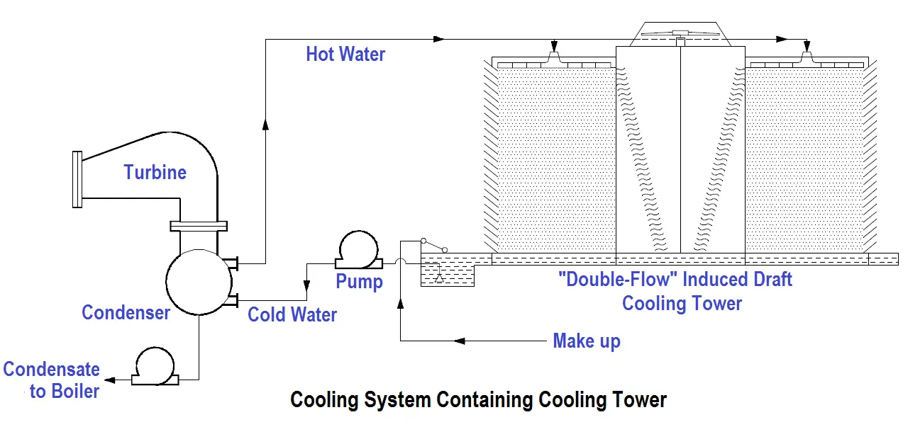
Figure 10 Cooling System Containing Cooling Tower
The cooling of the water in a cooling tower is accomplished by the direct contact of water and air. This cooling effect is provided primarily by an exchange of latent heat of vaporization resulting from evaporation of a small amount of water and by a transfer of sensible heat, which raises the temperature of the air. The heat transferred from the water to the air is dissipated to the atmosphere.
Induced Draft Cooling Towers
Induced draft cooling towers, illustrated in Figure 11, are constructed such that the incoming circulating water is dispersed throughout the cooling tower via a spray header. The spray is directed down over baffles that are designed to maximize the contact between water and air. The air is drawn through the baffled area by large circulating fans and causes the evaporation and the cooling of the water.

Figure 11 Induced Draft Cooling Tower
The nomenclature for induced draft cooling towers, including some items not illustrated in Figure 11 is summarized below.
Casing – The casing encloses the walls of the cooling tower, exclusive of fan deck and louvers.
Collecting basin – The collecting basin is a receptacle beneath the cooling tower for collecting the water cooled by the cooling tower. It can be made of concrete, wood, metal, or an alternative material. Certain necessary accessories are required such as sump, strainers, overflow, drain, and a makeup system.
Drift eliminators – The drift eliminators are parallel blades of PVC, wood, metal, or an alternative material arranged on the air discharge side of the fill to remove entrained water droplets from the leaving air stream.
Driver – The driver is a device that supplies power to turn the fan. It is usually an electric motor, but turbines and internal combustion engines are occasionally used.
Drive shaft – The drive shaft is a device, including couplings, which transmits power from the driver to the speed reducer.
Fan – The fan is a device used to induce air flow through the cooling tower.
Fan deck – The fan deck is a horizontal surface enclosing the top of the cooling tower above the plenum that serves as a working platform for inspection and maintenance.
Fan stack – The fan stack is a cylinder enclosing the fan, usually with an eased inlet and an expanding discharge for increased fan efficiency.
Fill – The fill is PVC, wood, metal, or an alternative material that provides extended water surface exposure for evaporative heat transfer.
Intake louvers – The intake louvers are an arrangement of horizontal blades at the air inlets that prevent escape of falling water while allowing the entry of air.
Makeup valve – The makeup valve is a valve that introduces fresh water into the collection basin to maintain the desired collecting basin water level.
Overflow – The overflow is a drain that prevents the collecting basin from overflowing.
Partition – The partition is a baffle within a multicell cooling tower that is used to prevent air and/or water flow between adjacent cells.
Plenum – The plenum is the internal cooling tower area between the drift eliminators and the fans.
Speed reducer – The speed reducer is a right-angle gear box that transmits power to the fan while reducing the driver speed to that required for optimal fan performance.
Sump – The sump is a depressed portion of the collecting basin from which cold water is drawn to be returned to the connected system. The sump usually contains strainer screens, antivortex devices, and a drain or cleanout connection.
Distribution system – The distribution system is that portion of a cooling tower that distributes water over the fill area. It usually consists of one or more flanged inlets, flow control valves, internal headers, distribution basins, spray branches, metering orifices, and other related components.
Forced Draft Cooling Towers
Forced draft cooling towers are very similar to induced draft cooling towers. The primary difference is that the air is blown in at the bottom of the tower and exits at the top. Forced draft cooling towers are the forerunner to induced draft cooling towers. Water distribution problems and recirculation difficulties discourage the use of forced draft cooling towers.
Natural Convection Cooling Towers
Natural convection cooling towers, illustrated in Figure 12, use the principle of convective flow to provide air circulation. As the air inside the tower is heated, it rises through the tower. This process draws more air in, creating a natural air flow to provide cooling of the water. The basin at the bottom of the tower is open to the atmosphere. The cooler, more dense air outside the tower will flow in at the bottom and contribute to the air circulation within the tower. The air circulation will be self perpetuating due to the density difference between the warmer air inside and the cooler air outside.
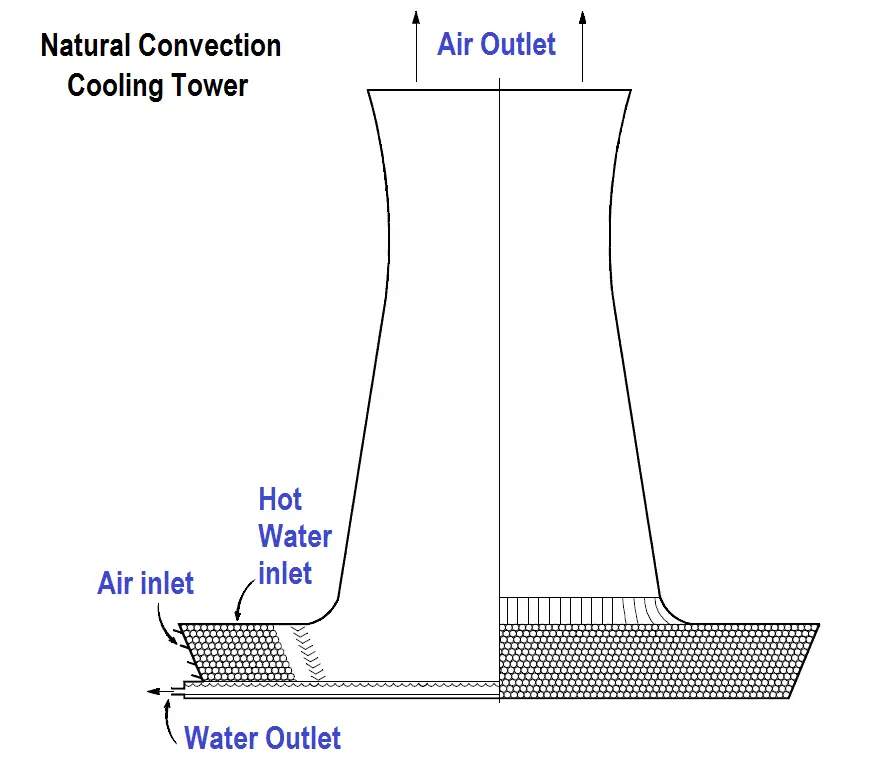
Figure 12 Natural Convection Cooling Tower
The incoming water is sprayed around the circumference of the tower and cascades to the bottom. The natural convection cooling towers are much larger than the forced draft cooling towers and cost much more to construct. Because of space considerations and cost, natural convection cooling towers are built less frequently than other types.
Cooling Towers Summary
The important information in this chapter is summarized below.
- The cooling tower removes heat from water used in cooling systems within the plant. The heat is released to the air rather than to a lake or stream. This allows facilities to locate in areas with less water available because the cooled water can be recycled. It also aids environmental efforts by not contributing to thermal pollution.
- Induced draft cooling towers use fans to create a draft that pulls air through the cooling tower fill. Because the water to be cooled is distributed such that it cascades over the baffles, the air blows through the water, cooling it.
- Forced draft cooling towers blow air in at the bottom of the tower. The air exits at the top of the tower. Water distribution and recirculation difficulties limit their use.
- Natural convection cooling towers function on the basic principle that hot air rises. As the air inside the tower is heated, it rises through the tower. This process draws more air in, creating a natural air flow to provide cooling of the water.


My cousin manages an oil factory, and it seems like they use a cooling tower to keep the factory inside cool while handling business operations. I appreciate you letting us know that cooling towers provide a cooling effect through an exchange of latent heat of vaporization due to a small amount of water evaporating and the transfer of sensible heat to raise the temperature of the air. I’ll take note of this explanation while I help my cousin find the cooling tower parts he needs for replacement soon.