Here we shall see recommended practices for the selection of the control valve for harsh process conditions.
Control Valve Recommended Practices
- The process design conditions should be as per the ANSI pressure rating and the material of the valve should be selected as per piping specifications for a particular project. The valve end connections and pressure rating should, as a minimum, conform to the piping specification. The valve material shall be suitable for the process conditions.
- Nickel alloy or stainless steel valve metallurgy should be specified for temperatures below -20 degrees F. High-pressure steam, flashing water applications, and boiler feed water service where differential pressures exceed 200 psi may require harder chrome-molybdenum alloys. Sour service valve materials must meet the requirements of NACE MR0175-90. Corrosive and erosive components even in trace quantities may affect the metallurgical choice of the valve.
- Trim material can be as per manufacturer standard but in high-pressure services, it should be checked for cavitation, flashing, and other unwanted phenomenons.
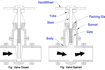
- Globe valves are usually accepted with flange type of end connection. For pressure rating above 900, they are generally butt welded. Threaded and welded end connections are not recommended for hydrocarbon services.
- Flanged control valve bodies are available with either integral flanges (machined as part of the body casting or forging, or flanges welded to the body), or separable flanges (individually removable flanges that usually lock in place on the valve body by means of a two-piece retaining ring).
- Flangeless valves have no flange connections as part of the valve body and are simply bolted or clamped between the adjoining line flanges. Long bolts used with flangeless valves can expand when exposed to fire and cause leakage. A fire detection shield and/or insulation are recommended. In addition, high-tensile strength bolting is required.
- The valve body size should be no less than two pipe sizes smaller than the line size. Smaller valve sizes must be reviewed to make sure that line mechanical integrity is not violated.
- Threaded seat rings should be avoided where possible because corrosion often makes removal difficult.
- Bonnets should be bolted. Bolting material should comply with ASTM A193/194/320 and should be compatible with the valve body and bonnet.
- Bonnet gaskets should be fully retained 316 SST spiral wound, with polytetrafloroethelene or graphite filler. Flat gaskets made from PTFE sheet stock are acceptable where conditions permit. Insert reinforcements should be 316 SST or other appropriate alloys, as required.
- Packing boxes should be easily accessible for periodic adjustment.
The packing material should
(1) be elastic and easily deformable,
(2) be chemically inert,
(3) be able to withstand applicable process conditions,
(4) provide a degree of fire resistance,
(5) minimize friction, and
(6) reduce fugitive emissions to meet regulatory requirements.
The valve manufacturer’s packing temperature limits refer to the temperature at the packing box.
- PTFE has excellent inertness, good lubricating properties, and is one of the most popular valve packing materials. It may be used in solid molded, braided, or turned form (Vrings) or as a lubricant for asbestos-free packing. Its temperature limit with standard packing box construction is 450 F. If used to meet fugitive emissions, virgin PTFE should be alternated with carbon-filled PTFE or similar minimal cold-flowing material and live loaded.
- Graphite laminated or preformed ring packing is chemically inert except when strong oxidizers are handled. This type of packing can be used for temperature applications approaching 2000 F. The biggest difficulty caused by this type of packing is very high packing friction, which often requires an oversized actuator. Performance is often compromised, because of significant increases in hysteresis and deadband.
- Control valves should have no less than a Class II leakage rating. For most services, a Class IV rating is adequate. Class VI ratings should be considered only for applications requiring minimum possible leakage, and then only with owner approval.
- Single-seated globe valves with metal-to-metal seating surfaces meet Class IV. Class V shutoff can be achieved by providing an improved plug to seat ring concentricity or lapping seating surfaces and/or increasing actuator thrust. Resilient seats on single-seated valves can provide Class VI shutoff.
- Control valve flow characteristics are determined principally by the design of the valve trim. The three inherent characteristics available are quick opening, linear, and equal percentage. A modified equal percentage characteristics generally falling between linear and equal percentage characteristics is sometimes available.
- Installed characteristics often differ significantly from inherent characteristics if the pressure drop across the control valve varies with the flow. As a result, equal percentage plugs are generally used for flow control applications because most of the system pressure drop is not across the control valve. Linear plugs are commonly used for applications where most of the system pressure drop occurs across the control valve.
- As part of valve selection, the overall system in which the valve is to be installed should be considered. A typical system (in addition to the control valves) includes a pump or compressor, which provides energy, and other types of refinery equipment, such as piping, exchangers, furnaces, and hand valves, which offer resistance to flow. Note that the differential pressure between the pump head curve and the system pressure drop curve is the amount of pressure available for the control valve. If no control valve were used, the flow would always be at the rate indicated by the intersection of the two curves.
The primary factors that should be known for accurate sizing are:
(1) The upstream and downstream pressures at the flow rates being considered.
(2) The temperature of the fluid.
(3) The fluid phase (gas, liquid, slurry) and the density of the fluid (specific gravity, specific weight, molecular weight).
(4) The viscosity (liquids).
(5) The vapor pressure and critical pressure (liquids).
(6) Specific heat ratio (gas).
(7) The compressibility factor (gas).
Read Next:
- Control Valves Course
- Valve Quiz Questions
- Control Valve Accessories
- Control Valve Stroke Test
- Valve Characteristics