Modbus is a very popular data communication protocol found in a variety of industrial and commercial systems, often associated with electric motor controls. This Tutorial will explore the basic concept of networked control for industrial devices, and then explore the details of the Modbus protocol itself.
One of the most common forms of computer used in industrial control is the Programmable Logic Controller or PLC. These devices are similar in function to microcontrollers but designed to be programmed using languages much simpler than assembly or C in order to allow technical personnel with limited programming experience to configure these controllers to perform useful automation tasks.
Hardwired Motor Control
We may begin our exploration of Modbus by first considering an example of a PLC-controlled motor system that does not employ Modbus.
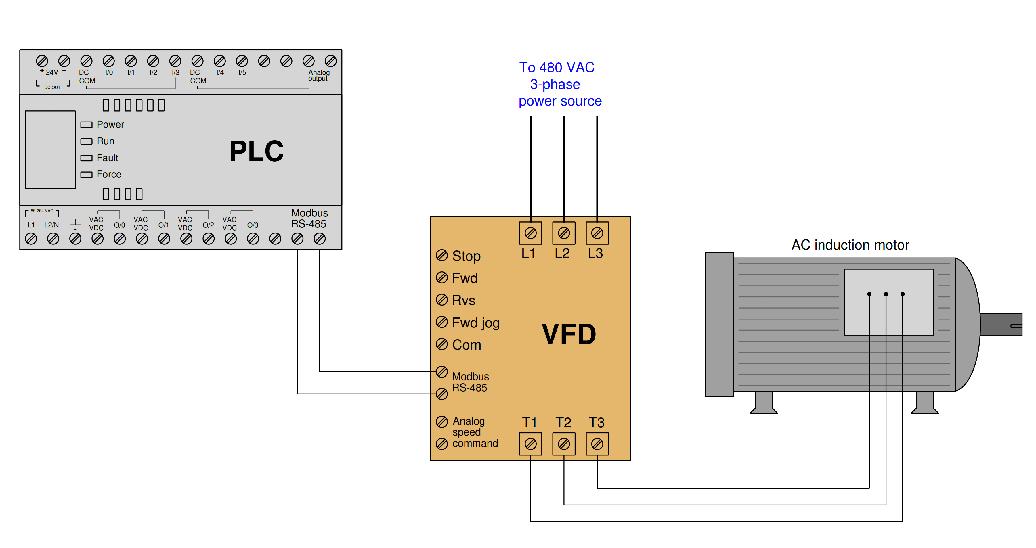
Here, the PLC sends individually-wired Forward, Reverse, and Stop, and speed-control command signals to a variable-frequency drive (VFD) which then sends three-phase power of varying frequency to an AC induction motor to do some useful task:

The discrete commands (e.g. Stop, Forward, Reverse) are nothing more than on/off contact closures provided by the PLC’s output channels to the VFD’s input terminals.
When the PLC commands the VFD to run in the Reverse direction, it simply activates output channel O/1 which closes a relay contact inside the PLC to connect the VFD’s “Rvs” terminal to the VFD’s “Com” terminal.
The VFD detects this electrical continuity and responds by running the motor in its reverse direction. Motor speed is commanded by an analog voltage signal (typically 0 to 10 Volts DC) output by the PLC, with 0 Volts representing zero speed and 10 Volts representing full speed.
The VFD receives this analog voltage signal and responds to it by outputting the appropriate frequency of three-phase AC power to the induction motor. While this system is certainly functional, it does not represent the only way for the PLC to issue commands to the VFD to control the motor.
Instead of using discrete conductors for each motor function, it is possible to connect the PLC and VFD together with a digital network cable and issue commands as digital codes to do the same. One such digital network standard is Modbus, which we will see applied in the next section.
Motor Control using Modbus Communication
Now consider this updated motor control system, where the only connecting wires between the PLC and VFD is a single two-conductor cable between the Modbus/RS-485 terminals of both devices.
Note: RS-485 is one standard for serial data communication using Non-Return-to-Zero (NRZ) encoding of bits. Two un-grounded conductors convey a pulsed voltage signal between the connected devices with one polarity of a voltage representing a “0” bit and the other polarity representing a “1” bit.
The PLC functions as a Modbus master device while the VFD functions as a Modbus slave:
By using appropriate Modbus commands transmitted to the VFD, the PLC is able to issue all the same commands (e.g. Stop, Forward, Reverse, speed control) as before but using far fewer wires.
For example, Modbus command code 05 writes a single bit of data to the receiving device, allowing the PLC to send discrete-signal commands to the VFD one at a time.
When the PLC commands the VFD to run in the Reverse direction, it issues a 05 command followed by a “1” data bit addressed to the appropriate memory location inside the VFD reserved for the “Reverse” command bit.
When the PLC commands the VFD to change motor speed, it issues an 06 Modbus code (“write register”) followed by a 16-bit number representing the desired motor speed and the appropriate address within the VFD reserved for speed command.
Not only can the PLC issue all the same commands as before, but it may also read data from the VFD which it could not do before.
For example, if the VFD provides a memory location for storing fault codes (e.g. motor overcurrent, bus Undervoltage, etc.), the PLC may be programmed to issue an 03 Modbus code to read a single register (16-bit binary number) from that memory location within the VFD, and thereby monitor the status of the VFD to alert human technicians of potential problems, and/or to modify its own supervisory control of the motor.
Multiple Motors Control using Modbus Network
Another advantage of the Modbus communication standard is that it is designed to address multiple devices on the same network.
This means our hypothetical PLC is not limited to controlling and monitoring just one motor, but up to 247 separate Modbus slave devices on the same two-wire communication cable!
The following illustration shows how this might work for multiple motors:
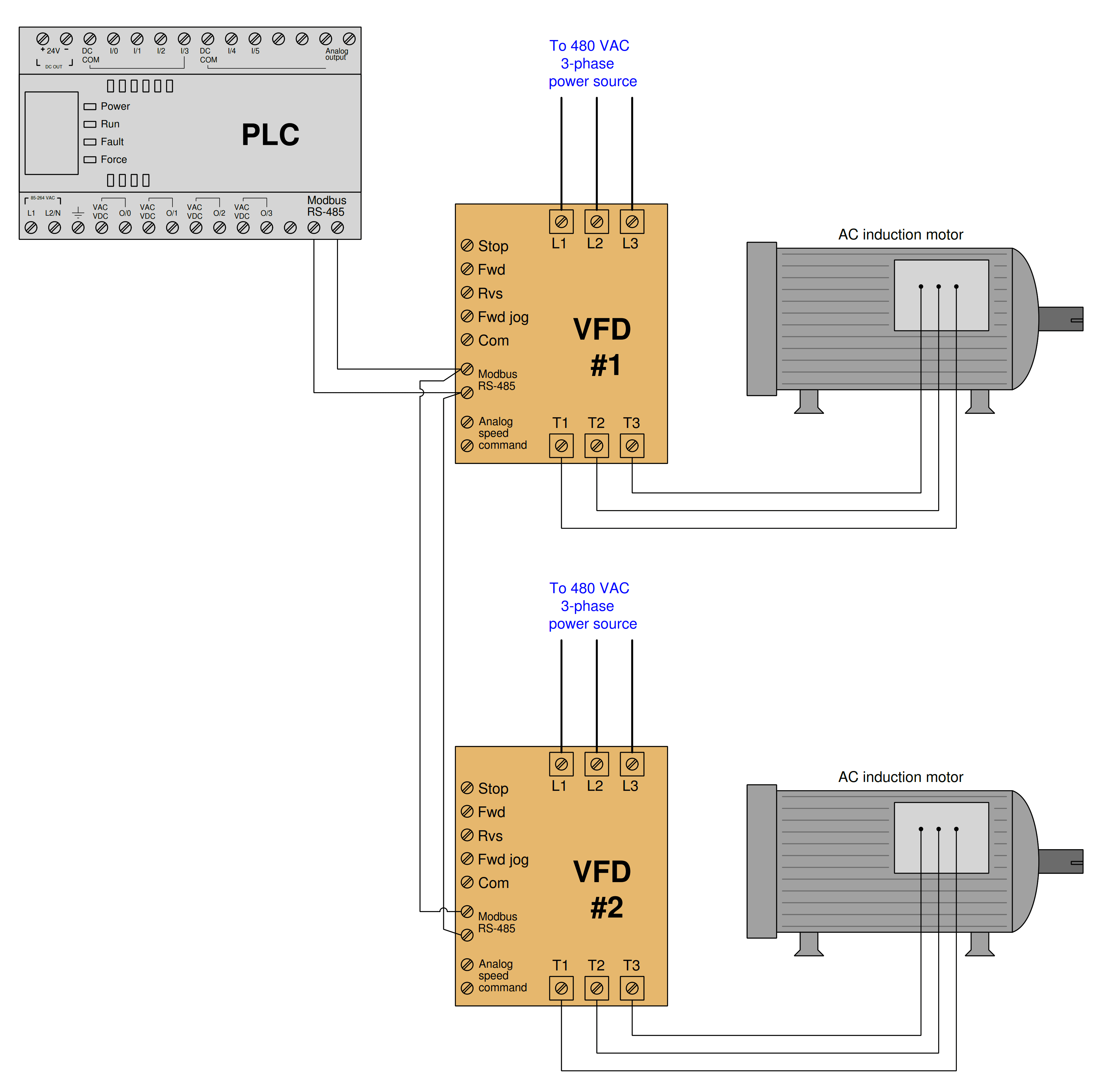
Each VFD is given its own Modbus network slave address, so that the PLC is able to distinguish between the two drives when communicating on the same wire pair.
Every Modbus code transmitted by the PLC contains this address as a single byte (8 bits) of data in order to make the receiving VFD aware that the code applies to it and not to any other Modbus device on the network.
In this example, we may wish to address VFD #1 with Modbus address 1, and VFD #2 with Modbus address 2. The Modbus standard provides a “broadcast address” of 0 which addresses all devices on the network simultaneously.
For example, if the PLC needed to start all motors in the same direction at once, it could issue a Modbus code 05 (write a single bit) to the same address inside each VFD representing the command bit for the correct direction of motor rotation.
So long as the VFDs are identically configured, the data will be received and interpreted by each VFD identically which will cause them to both start-up in the same direction.
Disadvantage of Modbus
The only disadvantages to using Modbus as opposed to dedicated wires for each sensing and control function are speed and reliability.
Modbus is necessarily slower than dedicated wire control because the PLC cannot simultaneously issue different commands on the network.
For example, if the PLC needed to tell a VFD to begin turning its motor in the forward direction at 1050 RPM, the Modbus-based system would need to issue two separate Modbus codes whereas the individually wired system could issue these commands all at once.
This disadvantage, however, is hardly worth considering if the Modbus network communicates at a reasonably high speed (thousands of bits per second).
The disadvantage of reliability may be readily perceived if we consider how each system would respond to a wiring fault (e.g. one wire coming loose and disconnected from a screw terminal).
In the individually-wired system, one wire fault disables one motor-control function but not necessarily any of the other functions. In the Modbus-based system, one wire fault disables everything because any Modbus communication requires the full function of that two-conductor communication cable.
The problem is even larger when multiple devices are controlled by the same Modbus cable: if a fault occurs between the controlling PLC and all the field devices, the PLC will lose control (and monitoring) for every one of those field devices! This is a factor worth considering when deciding whether or not to use any digital communication method for monitoring and control of multiple devices.
Modbus, especially when implemented over simple serial networks such as EIA/TIA-232 and EIA/TIA-485, is a rather primitive protocol. The seemingly arbitrary decimal codes used to issue commands and specify addresses are antiquated by modern standards.
For better or for worse, though, a great many digital industrial devices “speak” Modbus, even if they are also capable of communicating via other network protocols.
Using Modbus to communicate with modern control equipment is therefore an act of homage to 1970’s-era telecommunications: all participating devices in a Modbus network essentially behave the same as a 1970’s vintage Modicon PLC for the sake of exchanging information, even if their processing capabilities enable communications far more sophisticated than the Modbus protocol.
A Modbus device querying another Modbus device does not “know” how modern or antiquated that other device is because the basic Modbus standard has remained fixed for all this time.
Note: EIA/TIA-232 is also known by its older title RS-232. It is a Non-Return-to-Zero (NRZ) serial data protocol using ground-referenced voltage signals to represent “0” and “1” bits. These bits are transmitted one at a time at some constant bit rate and interpreted by the receiving device(s) before being assembled into whole digital words. The EIA/TIA-485 is also known by its older title RS-485.
© 2019-2021 by Tony R. Kuphaldt – under the terms and conditions of the Creative Commons Attribution 4.0 International Public License