A Variable Speed Drive (VSD) consists of a Motor and some form of controller. Early electric VSDs consisted of AC and DC motors combinations which were used as rotating controllers. The first electronic controllers used Thyristor (SCR) Rectifiers which controlled the voltage, and therefore the speed of DC motors. These DC VSDs are still widely used and offer very sophisticated control capabilities.
However, the DC motor is large, expensive, and requires periodic brush maintenance. The AC induction motor is simple, low-cost, reliable, and widely used throughout the world. In order to control the speed of an AC induction motor a more complex controller, usually called an inverter is required.
Induction Motor
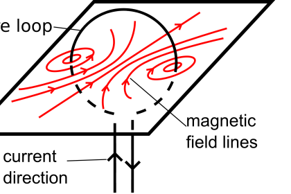
In order to understand how an inverter works, it is necessary to understand how an induction motor works. An induction motor works like a transformer. When the stator (the fixed, outer winding) is connected to a three-phase power source, a magnetic field that rotates at the frequency of the supply is set up.
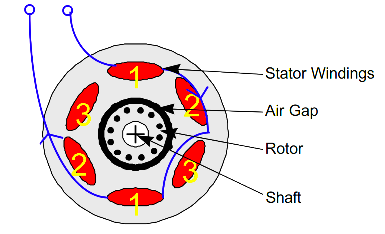
This field crosses the air gap between the stator and rotor and causes currents to flow in the rotor windings. This produces a force on the rotor as the current interacts with the changing magnetic field, and the rotor turns.
If the windings are arranged in several pairs (or poles), the frequency of the rotating field will be less than the applied frequency (e.g. two pole = 50/60Hz = 3000/3600rpm, but four pole = 50/60Hz = 1500/1800 rpm).
However, if the rotor runs at the same speed as the rotating field, there will be no changing magnetic field, and therefore no torque. Therefore the rotor always runs a little slower than the rotating field in order to generate torque. This difference in speed is known as slip.
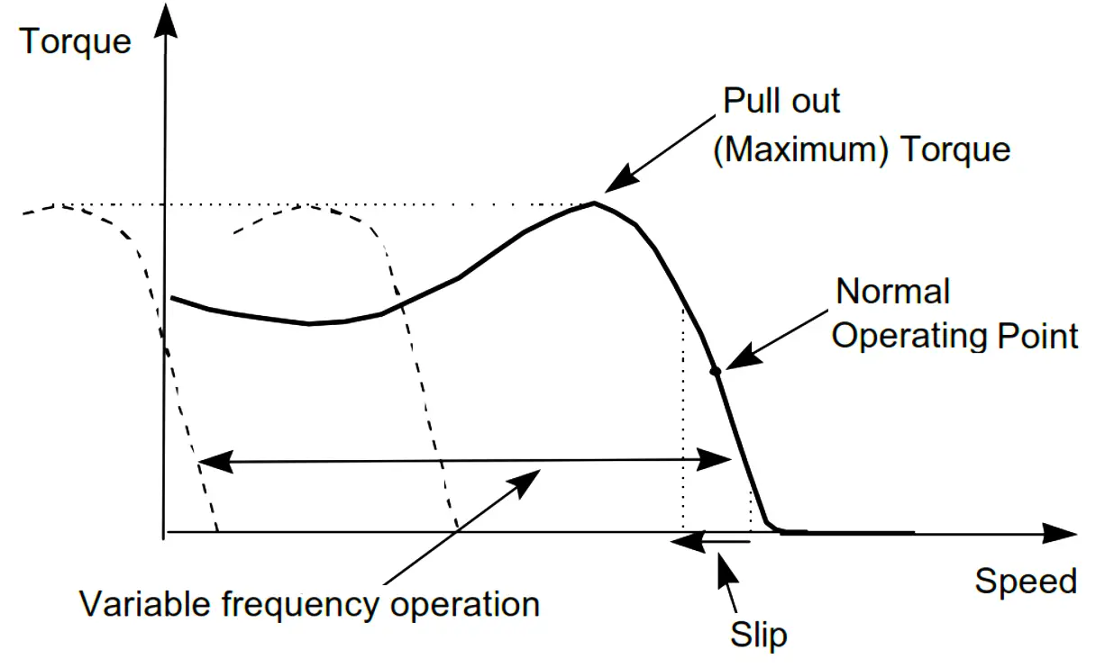
Hence the speed of the motor depends on the applied frequency, as well as the winding arrangement, and a little on the load.
Therefore in order to control the motor speed it is necessary to control the frequency of the supply. If the frequency is reduced, the voltage must be reduced or the magnetic flux will be too high and the motor will saturate.
Hence the voltage must be controlled as well. If the frequency is increased above normal, more voltage would normally be needed to maintain maximum flux; this is not usually possible, so less torque is available at high speed.
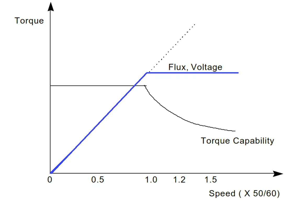
Therefore in order to control the speed of a standard AC motor, the applied frequency and voltage must be controlled.
Although it is difficult to control voltage and frequencies at these high powers, the use of a standard induction motor allows a cost-effective speed control system to be built.
Variable Frequency Inverter
An electronic converter that converts Direct Current (DC) to Alternating Current (AC) is known as an inverter. Electronic speed controllers for AC motors usually convert the AC supply to DC using a rectifier and then convert it back to a variable frequency, variable voltage AC supply using an inverter bridge.
The connection between the rectifier and inverter is called the DC link. The block diagram of a speed controller (often called an inverter) is shown below:
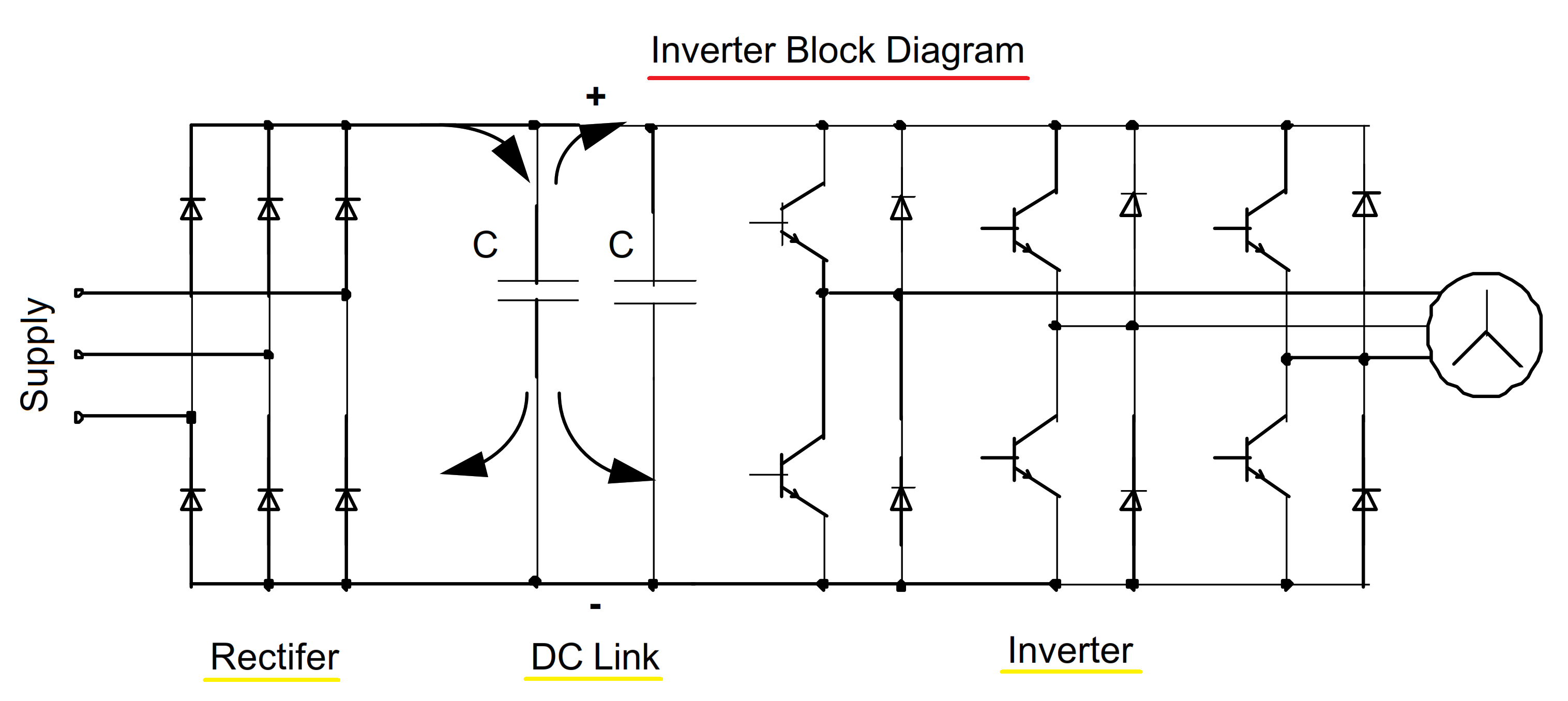
The supply, which can be single-phase (usually at low power) or three-phase is fed to a full wave rectifier which supplies the DC link capacitors. The capacitors reduce the voltage ripple (especially on single-phase supplies) and supply energy for short mains breaks.
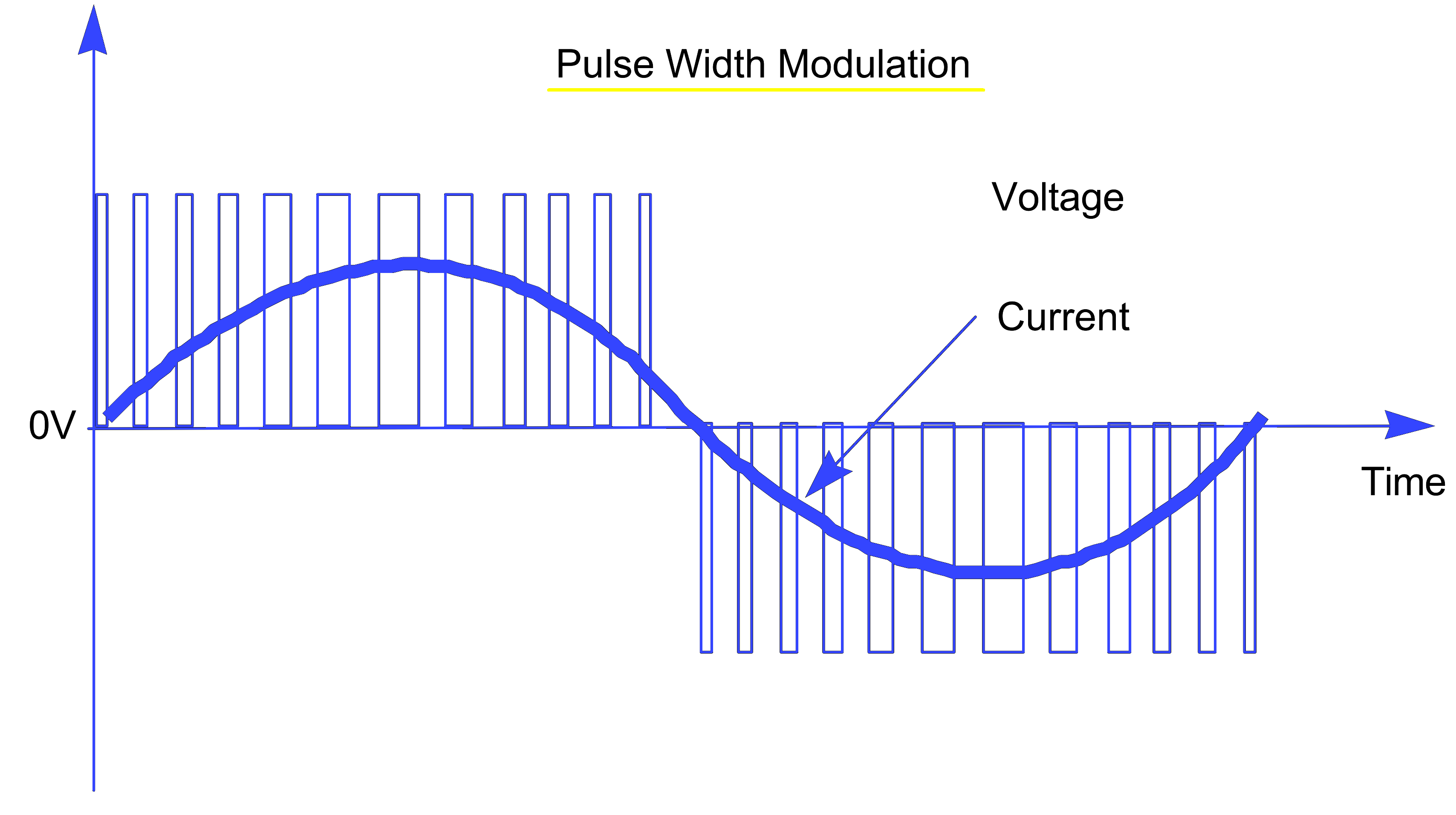
The voltage on the capacitors is uncontrolled and depends on the peak AC supply voltage. The DC voltage is converted back to AC using Pulse Width Modulation (PWM). The desired waveform is built up by switching the output transistors (Insulated Gate Bipolar Transistors; IGBTs) on and off at a fixed frequency (the switching frequency).
By varying the on and off time of the IGBTs the desired current can be generated, but the output voltage is still a series of square wave pulses. Pulse Width Modulation is shown in the figure below.
There are many complex aspects of inverters that need to be considered during the design:
- The control system to calculate the PWM requirements is very complex and specially designed integrated circuits (ASICs) are needed.
- The control electronics are often connected to the DC link, which is connected to the supply, so the customer connections, display, etc. must be safely isolated from this.
- The output current must be carefully monitored to protect the inverter and the motor during overload and short circuits.
- At first switch on the DC link capacitors are discharged, and the inrush current must be limited, usually using a resistor which is bypassed by a relay after a few seconds.
- All connections to the inverter, especially the supply and control connections, may carry a lot of interference and must be fitted with suitable protection components.
- An internal power supply with several different output voltages is needed for to supply the control electronics.
- The inverter, especially the IGBTs and rectifier diodes, produce heat which must be dissipated using a fan and heatsink.
- The PWM output voltage contains many high-frequency harmonics (because of the fast switching) and can be a major source of EMI.
- The input rectifier draws current only at the peak of the supply waveform, so the input currents have a poor form factor ( i.e. the RMS value can be quite high – this does not mean the inverter is inefficient!)
A practical inverter needs to be designed for ease of use and installation. Large inverters are often specially designed or engineered for each application; smaller inverters are designed for general-purpose use and are of standard design. Siemens Standard Drives division manufactures standard inverters up to 90kW for this purpose.
Read more about the pyrometers. Download the document from the below table.
| Title: | Siemens Standard Drives Handbook |
| Author: | Siemens |
| Format: | |
| Size: | 213 KB |
| Pages: | 92 |
| Download: | Click Here |
If you liked this article, then please subscribe to our YouTube Channel for PLC and SCADA video tutorials.
You can also follow us on Facebook and Twitter to receive daily updates.
Read Next:
- Electrical Enclosure eBook
- Valve Basics and Sizing Book
- Industrial Control System Guide
- Instrumentation Books Download
- pH and ORP Learning Handbook