Developed by the Modicon company (the original manufacturer of the Programmable Logic Controller, or PLC ) in 1979 for use in its industrial control products.
Modbus is a protocol designed specifically for exchanging process data between industrial control devices.
Background of Modbus
The Modbus standard does not specify any details of physical networking, and thus may be deployed on many different types of physical networks.
In other words, Modbus primarily falls within layer 7 of the OSI Reference Model (the so-called “Application Layer”) and therefore is compatible (Note 1) with any lower-level communication protocols including EIA/TIA-232, EIA/TIA-485, Ethernet (the latter via TCP/IP), and a special token-passing network also developed by Modicon called Modbus Plus.
The Modbus standard primarily defines the meaning of various Modbus commands, the addressing scheme used to place data within devices, and the formatting of the data.
Note 1: These Modbus data frames may be communicated directly in serial form, or “wrapped” in TCP segments and IP packets and Ethernet frames, or otherwise contained in any form of the packet-based protocol as needed to transport the data from one device to another. Thus, Modbus does not “care” how the data is communicated, just what the data means for the end-device.
Modbus consists of a set of standardized digital codes intended to read data from and write data to industrial devices. A Modbus-compliant industrial device has been programmed to understand these codes and respond to them appropriately when received.
The simplest Modbus codes read and write single bits of data in the device’s memory, for example, the status of a PLC input channel, PLC output channel, or status bit within a PLC program.
Other Modbus codes operate on 16-bit words of data, useful for reading and writing counter and timer accumulated values, operands for mathematical instructions, converted analog signals, etc.
Early implementations of Modbus used EIA/TIA-485 as the network physical layer, which is strictly a layer 1 protocol. This meant that Modbus needed to specify a channel arbitration scheme in order to negotiate communications with multiple devices on a network. The arbitration chosen was master/slave, where one PLC functioned as the master Modbus device and all other devices functioned as Modbus slaves.
Interestingly, this vestige of master/slave arbitration survives to this day, even when Modbus commands are communicated via networks with their own differing arbitration methods.
For example, Modbus commands communicated over Ethernet still reference “slave” addresses even though the Ethernet network those messages are sent over uses CSMA/CD arbitration.
In other words, there is a hint of OSI layer 2 embedded within Modbus messages that still dictates which Modbus devices may issue commands and which must obey commands.
Modbus Data Frames
The Modbus communication standard defines a set of commands for reading (receiving) and writing (transmitting) data between a master device and one or more slave devices connected to the network.
Each of these commands is referenced by a numerical code, with addresses of the master and slave devices’ internal registers (data sources and data destinations) specified along with the function code in the Modbus frame.
Modbus standard
Two different formats are specified in the Modbus standard:
- ASCII
- RTU
The difference between these two modes is how addresses, function codes, data, and error-checking bits are represented.
Modbus ASCII Mode
In Modbus ASCII mode, all slave device addresses, function codes, and data are represented in the form of ASCII characters (7 bits each), which may be read directly by any terminal program (e.g. minicom, Hyperterminal, kermit, etc.) intercepting the serial data stream.
This makes troubleshooting easier: to be able to directly view the Modbus data frames in human-readable form.
Modbus RTU Mode
In Modbus RTU mode, all slave device addresses, function codes, and data are expressed in raw binary form. Different error-checking techniques are used for ASCII and RTU modes as well.
The following diagram compares data frames for the two Modbus modes:
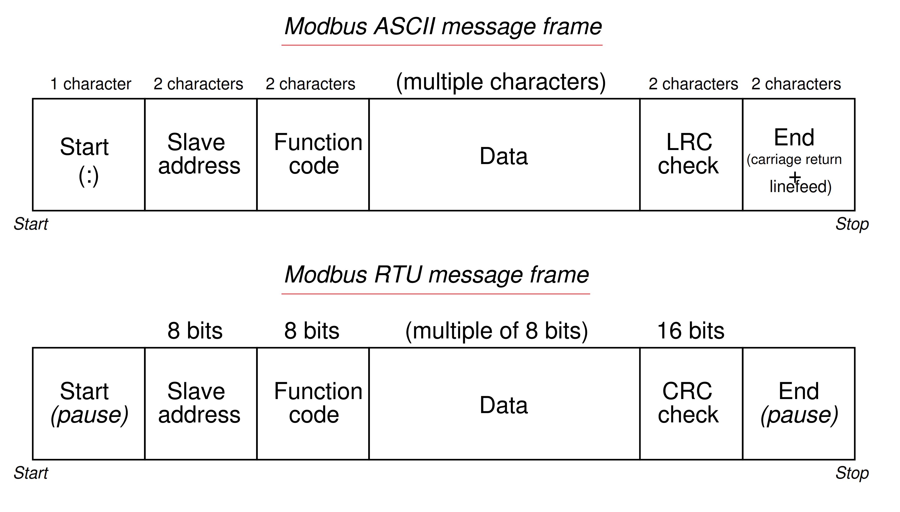
As you can see from a comparison of the two frames, ASCII frames require nearly twice (Note 2) the number of bits as RTU frames, making Modbus ASCII slower than Modbus RTU for any given data rate (bits per second).
The contents of the “Data” field vary greatly depending on which function is invoked, and whether or not the frame is issued by the master device or from a slave device. The next article lists the data frame format for multiple Modbus function codes.
Since Modbus is strictly a “layer 7” protocol, these message frames are usually embedded within other data frames specified by lower-level protocols. For example, the Modbus TCP standard encapsulates individual Modbus data frames as TCP/IP segments/packets, which are then (usually) encapsulated again as Ethernet frame data payloads to arrive at the destination device.
This “multilayered” approach inherent to Modbus being such a high-level protocol may seem cumbersome, but it offers great flexibility in that Modbus frames may be communicated over nearly any kind of virtual and physical network type.
Additionally, RTU data frames use quiet periods (pauses) as delimiters, while ASCII data frames use three ASCII characters in total to mark the start and stop of each frame, at a “cost” of 21 additional bits. These additional delimiting bits do serve a practical purpose, though: they format each Modbus ASCII data frame as its own line on the screen of a terminal program.
Note 2 – Recall that each ASCII character requires 7 bits to encode. This impacts nearly every portion of the Modbus data frame. Slave address and function code portions, for example, require 14 bits each in ASCII but only 8 bits each in RTU.
The data portion of a Modbus ASCII frame requires one ASCII character (7 bits) to represent each hexadecimal symbol that in turn represents just 4 bits of actual data. The data portion of a Modbus RTU frame, by contrast, codes the data bits directly (i.e. 8 bits of data appear as 8 bits within that portion of the frame).
© 2019-2021 by Tony R. Kuphaldt – under the terms and conditions of the Creative Commons Attribution 4.0 International Public License