Learn the PLC programming for garden sprinkler system to operate in four zones and the watering will be done using timer automation.
Note: These PLC example codes are mainly suited for the students and engineers to learn and practice the ladder logic.
Garden sprinkler System
Problem Statement:
Design a PLC ladder logic for the following application.
There is a garden water sprinkler system with 4 zones. Zone 1 should operate for 15 seconds, then Zone 2 should operate for 15 seconds, then Zone 3 should operate for 15 seconds, then Zone 4 should operate for 15 seconds.
The system will operate only if it is not raining and there is no one in that particular zone.
PLC Training Series Step-by-Step
The automation community provides the best PLC training series with a step-by-step approach. Try for free of cost.
This PLC program video explains the water sprinkler problem and its solution.
Inputs and Outputs
Digital Inputs:
Start Button: I0.0
Digital Outputs:
Zone 1: Q0.0
Zone 2: Q0.1
Zone 3: Q0.2
Zone 4: Q0.3
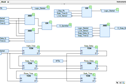
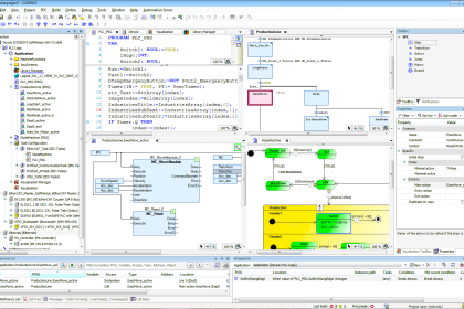
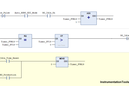
PLC Programming
Program Description
We have used Normally Open Contact for the Start Button (I0.0).
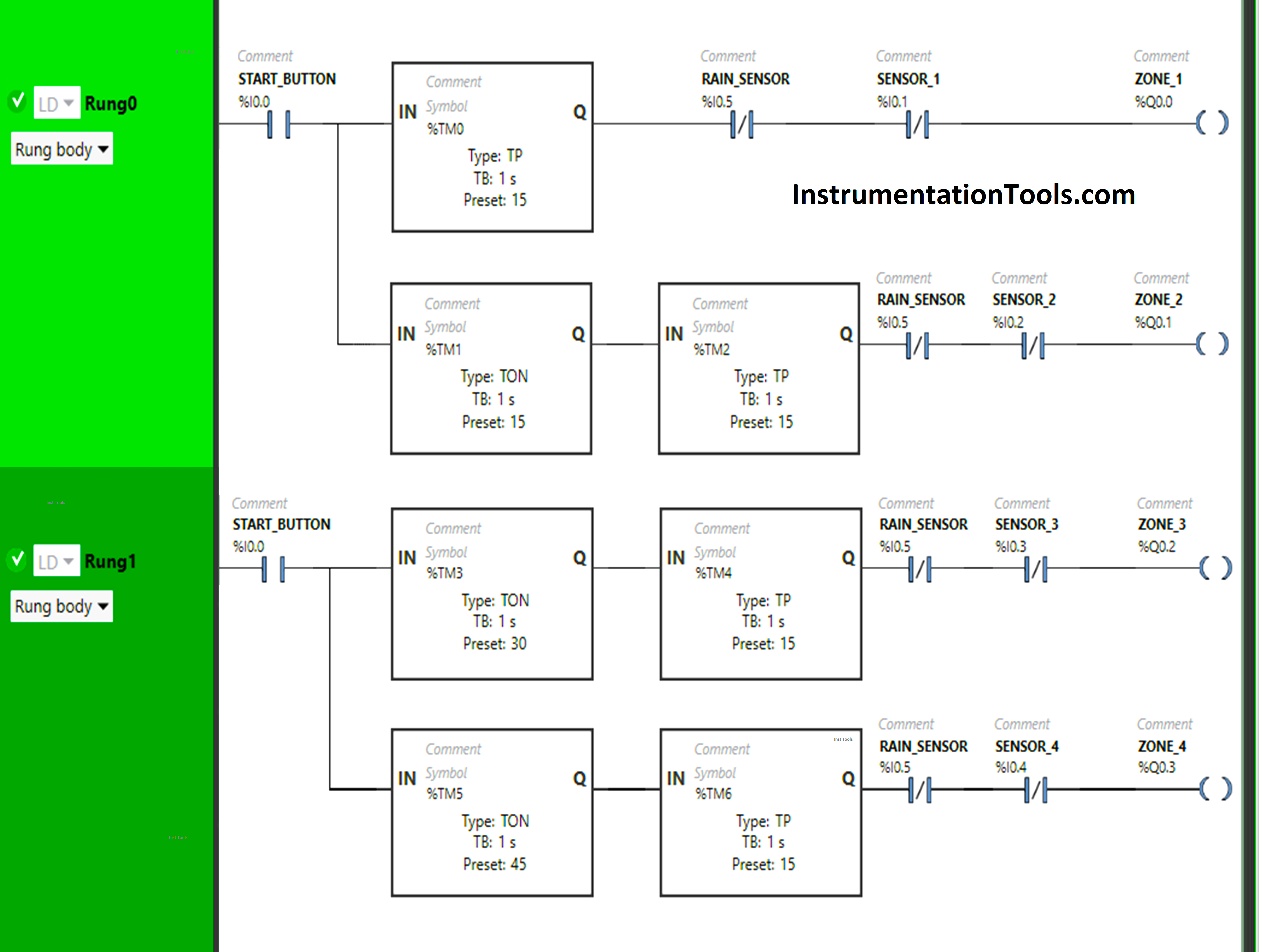
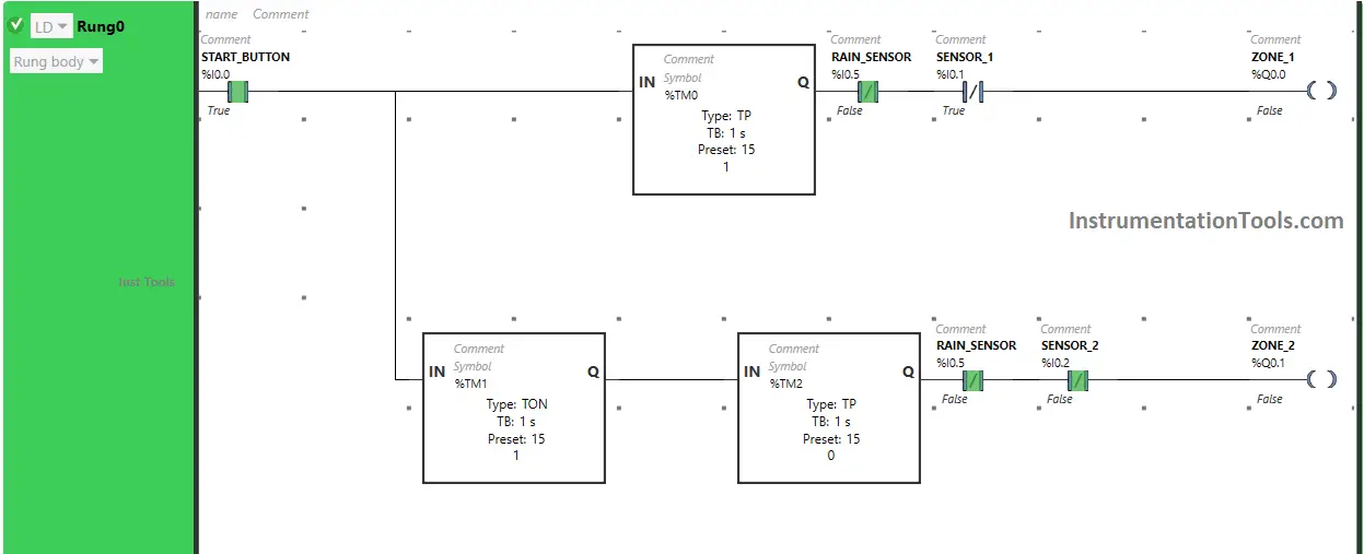
In Rung 0:
- Normally Open Contact is used for the Start Button (I0.0) to Turn ON the outputs Zone 1 (Q0.0) and Zone 2 (Q0.1).
- Timer Function Block type TP is used to Turn ON the output Zone 1 (Q0.0) for a limited time.
- Timer Function Block type TON is used to delay the turning ON time of the output Zone 2 (Q0.1) for some time.
- Timer Function Block type TP is used to Turn ON the output Zone 2 (Q0.1) for a limited time.
- Normally Closed Contacts are used for Rain Sensors (I0.5) to turn OFF the outputs of Zone 1 (Q0.0) and Zone 2 (Q0.1).
- Normally Closed Contact is used for Sensor 1 (I0.1) to turn OFF the output Zone 1 (Q0.0).
- Normally Closed Contact is used for Sensor 2 (I0.2) to turn OFF the output Zone 2 (Q0.1).
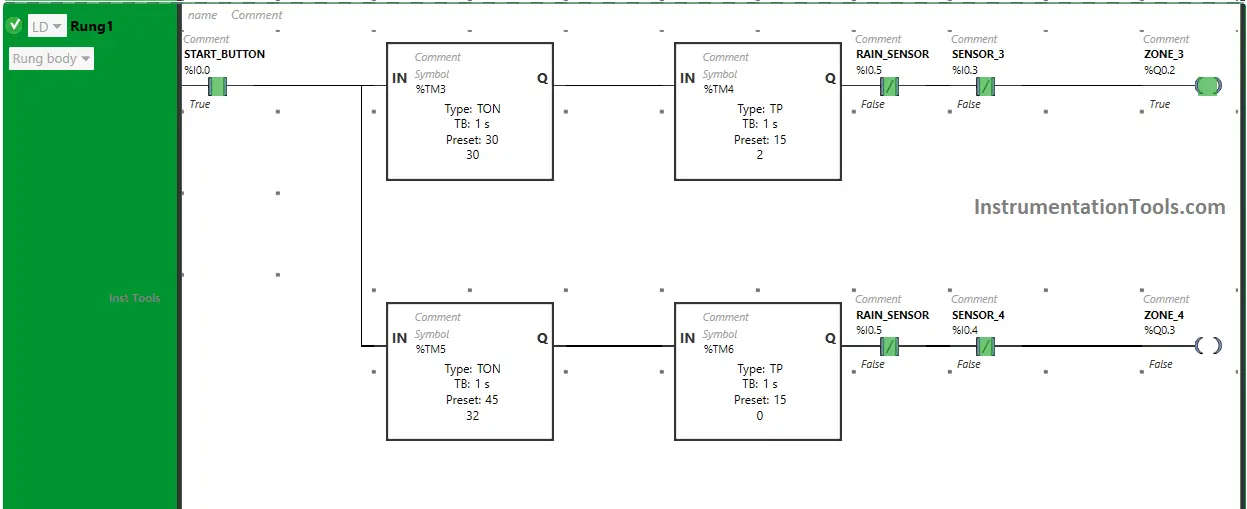
In Rung 1:
- Normally Open Contact is used for the Start Button (I0.0) to Turn ON the outputs Zone 3 (Q0.2) and Zone 4 (Q0.3).
- Timer Function Block type TON is used to delay the turning ON time of the output Zone 3 (Q0.2) for some time.
- Timer Function Block type TP is used to Turn ON the output Zone 3 (Q0.2) for a limited time.
- Timer Function Block type TON is used to delay the turning ON time of the output Zone 4 (Q0.3) for some time.
- Timer Function Block type TP is used to Turn ON the output Zone 4 (Q0.3) for a limited time.
- Normally Closed Contacts are used for Rain Sensors (I0.5) to turn OFF the outputs of Zone 3 (Q0.2) and Zone 4 (Q0.3).
- Normally Closed Contact is used for Sensor 3 (I0.3) to turn OFF the output Zone 3 (Q0.2).
- Normally Closed Contact is used for Sensor 4 (I0.4) to turn OFF the output Zone 4 (Q0.3).
Program Simulation
We will simulate the PLC program and discuss the results. We may show the partial logic instead of the complete program in the below test cases. Watch the above video to learn this programming.
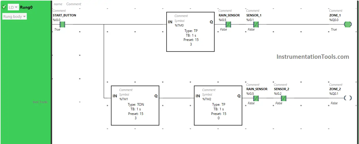
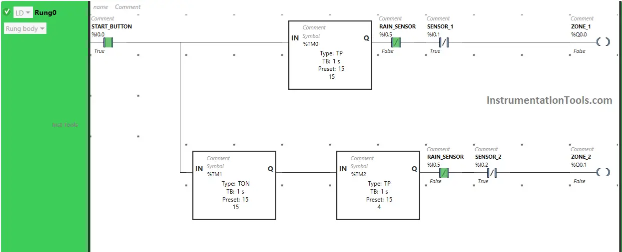
Rung 0:
When the Start Button (I0.0) is turned ON, the output Zone 1 (Q0.0) turns ON (Garden sprinkler system starts in Zone 1) but for a limited time as Timer Function type TP is used to turn ON the Output Zone 1 (Q0.0) or Start the Garden Sprinkle system in Zone 1 for a limited time. The time is set to 15 seconds.
So after 15 seconds, the output Zone 1 (Q0.0) will turn OFF, or after 15 seconds Garden sprinkler system in Zone 1 stops.
Also, when Start Button (I0.0) is turned ON, the output Zone 2 (Q0.1) will turn ON after 15 seconds, or the Garden sprinkler system will start in Zone 2 after 15 seconds i.e immediately after the output Zone 1 (Q0.0) is turned OFF or (after Garden sprinkler system in Zone 1 stops) because Timer Function Block TON is used to delay the turning ON time of the output Zone 2 (Q0.1). The time is set to 15 seconds.
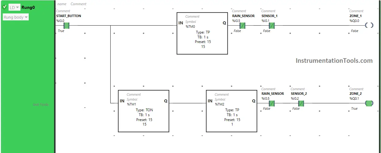
After 15 seconds, the output Zone 2 (Q0.1) will turn ON, or after 15 seconds Garden sprinkler system starts in Zone 2 but for a limited time as Timer Function Block type TP is used to turn ON the output Zone 2 (Q0.1) for a limited time. The time is set to 15 seconds.
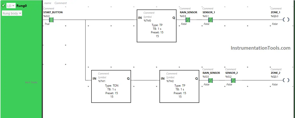
After 15 seconds, the output Zone 2 (Q0.1) turns OFF, or after 15 seconds the Garden sprinkler system in Zone 1 stops.
If Rain sensor (I0.5) gets activated in Rung0 (Rain starts), the outputs in Rung0 Zone 1 (Q0.0) and Zone 2 (Q0.1) will remain OFF or will turn OFF (Garden sprinkler system in Zone 1 and Zone 2 will not start or will turn OFF if it was started).
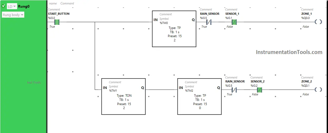
If Sensor 1 gets activated in Rung0 (Sensor detects movement in Zone 1), the output Zone 1 (Q0.0) will remain OFF or will turn OFF (Garden sprinkler system in Zone 1 will not start or will turn OFF if it was started).
If Sensor 2 gets activated in Rung0 (Sensor detects movement in Zone 2), the output Zone 2 (Q0.1) will remain OFF or will turn OFF (Garden sprinkler system in Zone 2 will not start or will turn OFF if it was started).
Rung 1:
When the Start Button (I0.0) is turned ON, the output Zone 3 (Q0.2) turns ON after 30 seconds, or after 30 seconds the Garden sprinkler system starts in Zone 3 i.e immediately after the output Zone 2 (Q0.1) is turned OFF or (after Garden sprinkler system in Zone 2 stops) because Timer Function Block TON is used to delay the turning ON time of the output Zone 3 (Q0.2). The time is set to 30 seconds.
After 30 seconds, the output Zone 3 (Q0.2) will turn ON, or after 30 seconds Garden sprinkler system in Zone 3 starts but for a limited time as Timer Function Block type TP is used to turn ON the output Zone 3 (Q0.2) for limited time. The time is set to 15 seconds.
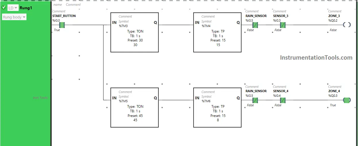
After 15 seconds, the output Zone 3 (Q0.2) turns OFF, or after 15 seconds Garden sprinkler system in Zone 3 stops.
Also, when Start Button (I0.0) is turned ON, the output Zone 4 (Q0.3) will turn ON after 45 seconds, or the Garden sprinkler system will start in Zone 4 after 45 seconds i.e immediately after the output Zone 3 (Q0.2) is turned OFF or (after Garden sprinkler system in Zone 3 stops) because Timer Function Block TON is used to delay the turning ON time of the output Zone 4 (Q0.3). The time is set to 45 seconds.
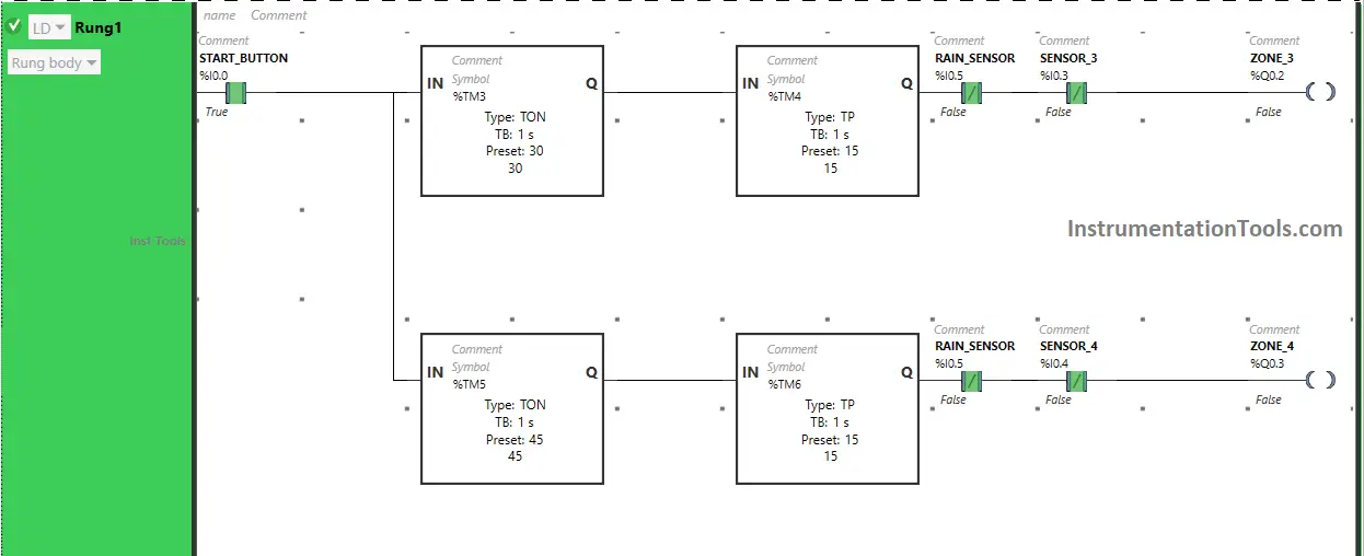
After 45 seconds, the output Zone 4 (Q0.3) will turn ON, or after 45 seconds Garden sprinkler system starts in Zone 4 but for a limited time as Timer Function Block type TP is used to turn ON the output Zone 4 (Q0.3) for a limited time. The time is set to 15 seconds.
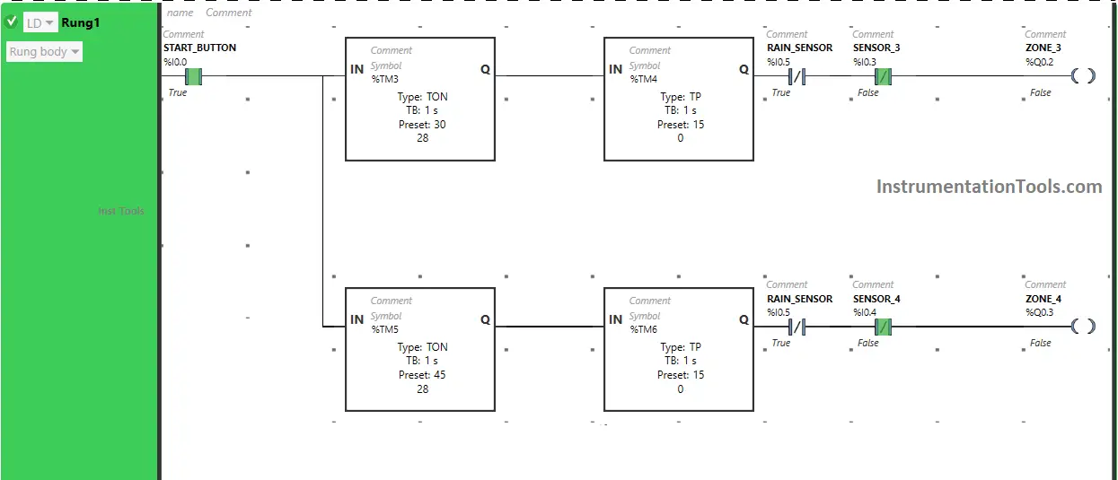
After 15 seconds, the output Zone 4 (Q0.3) turns OFF, or after 15 seconds Garden sprinkler system in Zone 4 stops.
If Rain sensor (I0.5) gets activated in Rung1 (Rain starts), the outputs in Rung1 Zone 3 (Q0.2) and Zone 4 (Q0.3) will remain OFF or will turn OFF (Garden sprinkler system in Zone 3 and Zone 4 will not start or will turn OFF if it was started).
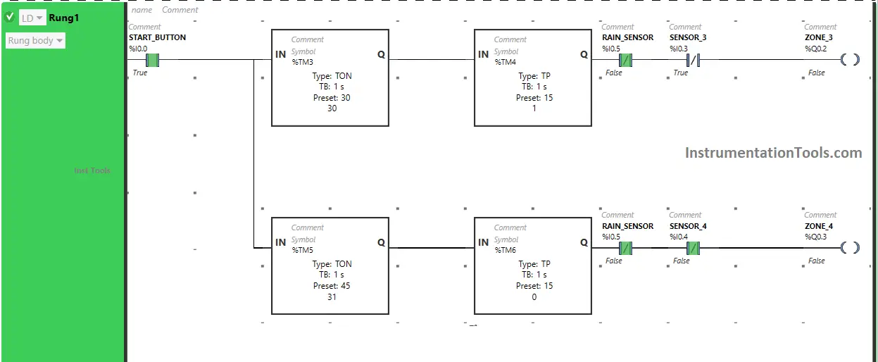
If Sensor 3 gets activated in Rung1 (Sensor detects movement in Zone 3), the output Zone 3 (Q0.2) will remain OFF or will turn OFF (Garden sprinkler system in Zone 3 will not start or will turn OFF if it was started).
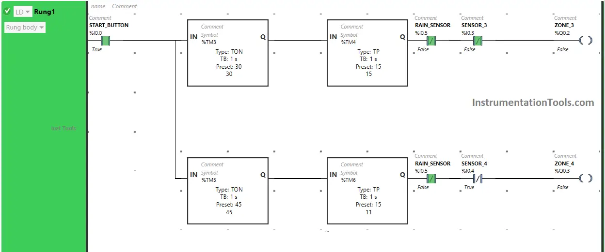
If Sensor 4 gets activated in Rung1 (Sensor detects movement in Zone 4), the output Zone 4 (Q0.3) will remain OFF or will turn OFF (Garden sprinkler system in Zone 4 will not start or will turn OFF if it was started).
If you liked this article, please subscribe to our YouTube Channel for PLC and SCADA video tutorials.
You can also follow us on Facebook and Twitter to receive daily updates.
Read Next:
- FIFO Queue in STL Language in Siemens PLC
- Searching the Tag number in Siemens PLC Program
- PID Controllers in Closed Loop Control Systems
- Instrumentation Engineer Detail Design Phase
- How to Use Diagnostic Buffer for SIEMENS PLC?