Inst ToolsInst ToolsInst Tools
  • Courses
  • Automation
    • PLC
    • Control System
    • Safety System
    • Communication
    • Fire & Gas System
  • Instrumentation
    • Design
    • Pressure
    • Temperature
    • Flow
    • Level
    • Vibration
    • Analyzer
    • Control Valve
    • Switch
    • Calibration
    • Erection & Commissioning
  • Interview
    • Instrumentation
    • Electrical
    • Electronics
    • Practical
  • Q&A
    • Instrumentation
    • Control System
    • Electrical
    • Electronics
    • Analog Electronics
    • Digital Electronics
    • Power Electronics
    • Microprocessor
  • Request
Search
  • Books
  • Software
  • Projects
  • Process
  • Tools
  • Basics
  • Formula
  • Power Plant
  • Root Cause Analysis
  • Electrical Basics
  • Animation
  • Standards
  • 4-20 mA Course
  • Siemens PLC Course
Reading: How to Work with Allen Bradley RsLogix Emulator?
Share
Font ResizerAa
Inst ToolsInst Tools
Font ResizerAa
  • Courses
  • Design
  • PLC
  • Interview
  • Control System
Search
  • Courses
  • Automation
    • PLC
    • Control System
    • Safety System
    • Communication
    • Fire & Gas System
  • Instrumentation
    • Design
    • Pressure
    • Temperature
    • Flow
    • Level
    • Vibration
    • Analyzer
    • Control Valve
    • Switch
    • Calibration
    • Erection & Commissioning
  • Interview
    • Instrumentation
    • Electrical
    • Electronics
    • Practical
  • Q&A
    • Instrumentation
    • Control System
    • Electrical
    • Electronics
    • Analog Electronics
    • Digital Electronics
    • Power Electronics
    • Microprocessor
  • Request
Follow US
All rights reserved. Reproduction in whole or in part without written permission is prohibited.
Inst Tools > Blog > PLC Tutorials > How to Work with Allen Bradley RsLogix Emulator?

How to Work with Allen Bradley RsLogix Emulator?

To work with Allen Bradley Emulator you need three softwares. Rslogix 500, Rslinx for communication, and Emulator to test the PLC logic.

Last updated: March 4, 2021 11:12 am
Editorial Staff
PLC Tutorials
No Comments
Share
3 Min Read
SHARE

In this article, I will cover how to work with an emulator in the Rslogix 500 of Allen-Bradley PLC.

Many people face an issue while working with Rslogix500 and its emulator.

Always note that if you want to work with an emulator or want to write the PLC program you always have to open the software as an administrator.

Allen Bradley RsLogix Emulator

To work with Rslogix 500 you need three software.

  1. Rslogix 500
  2. Rslinx for communication,
  3. Emulator to test the logic.

Let’s see how we can test the logic using the emulator by following the below steps.

Step 1:

Open Rslogix500, rslinx and Rslogix 500 emulator as an administrator.

First, go to Rslogix500 and create a new project. Enter in the programming environment.
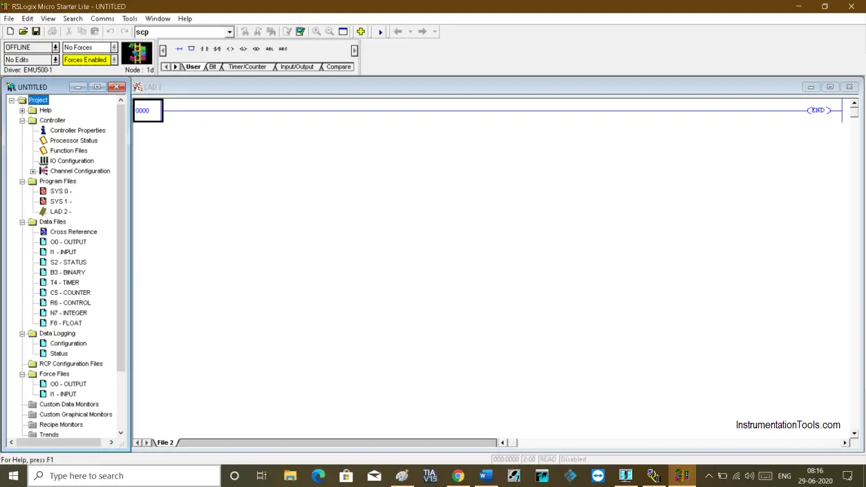
rslogix500

Step 2:

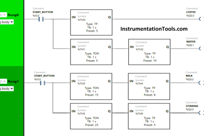
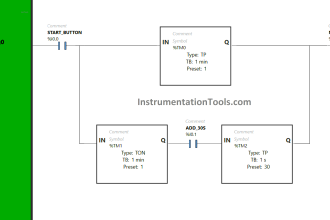
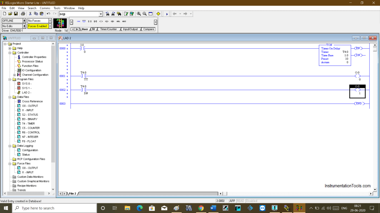
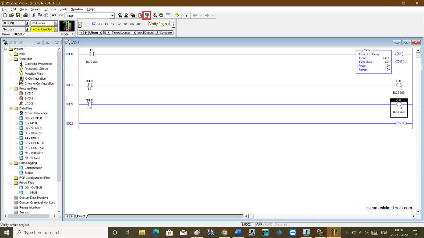
Write the program to test the PLC logic.

Here, I will write a program to energize an output for ten seconds and other output to energize after 10 seconds.

Rslogix 500 Emulator

Step 3:

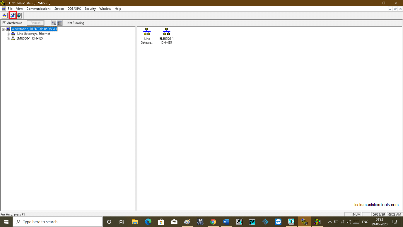
To test the logic, go to Rslinx. Click on an icon as shown in the red square.

Rslinx

Step 4:

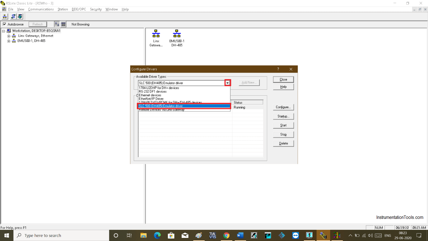
The following window will open up. Click on the drop-down menu and select an option as shown in the below window.

SLC 500 Emulator Driver

Step 5:

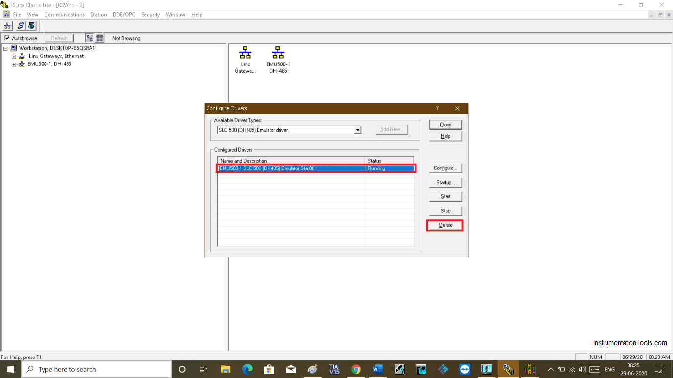
If you already see emulator is added to the configured device then select it and delete it as you can see in the below window.

After deleting it, do follow the same step as above to select an emulator.

Linx Gateway

Step 6:

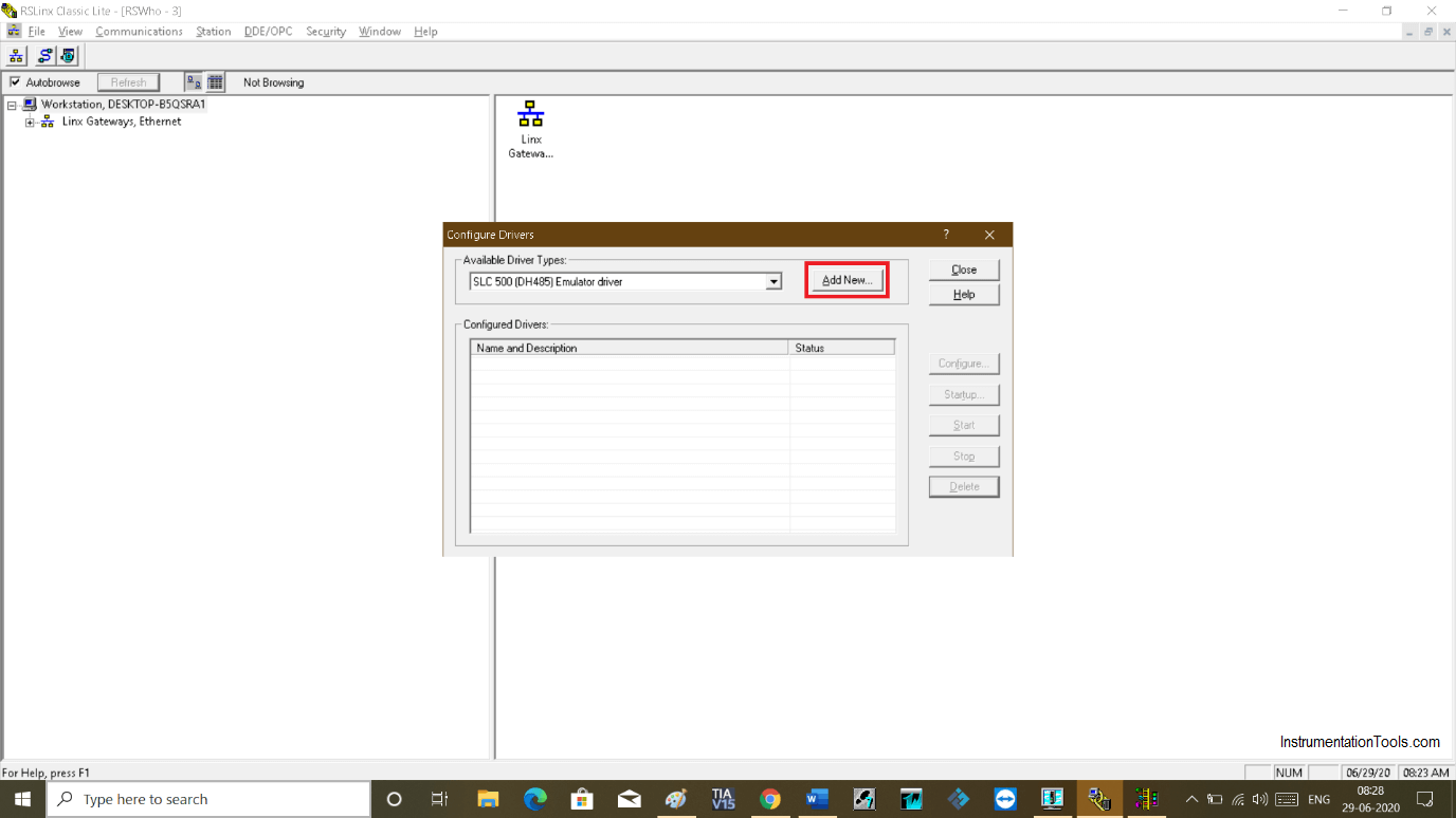
After selection click on “add new” to add it to the configured devices list.

Hit “close” to proceed. Communication is established now.

Allen Bradley PLC Emulator

Step 7:

Now go to Rslogix 500 to test the logic. Click on the icon as you can see in the red square to verify the logic.
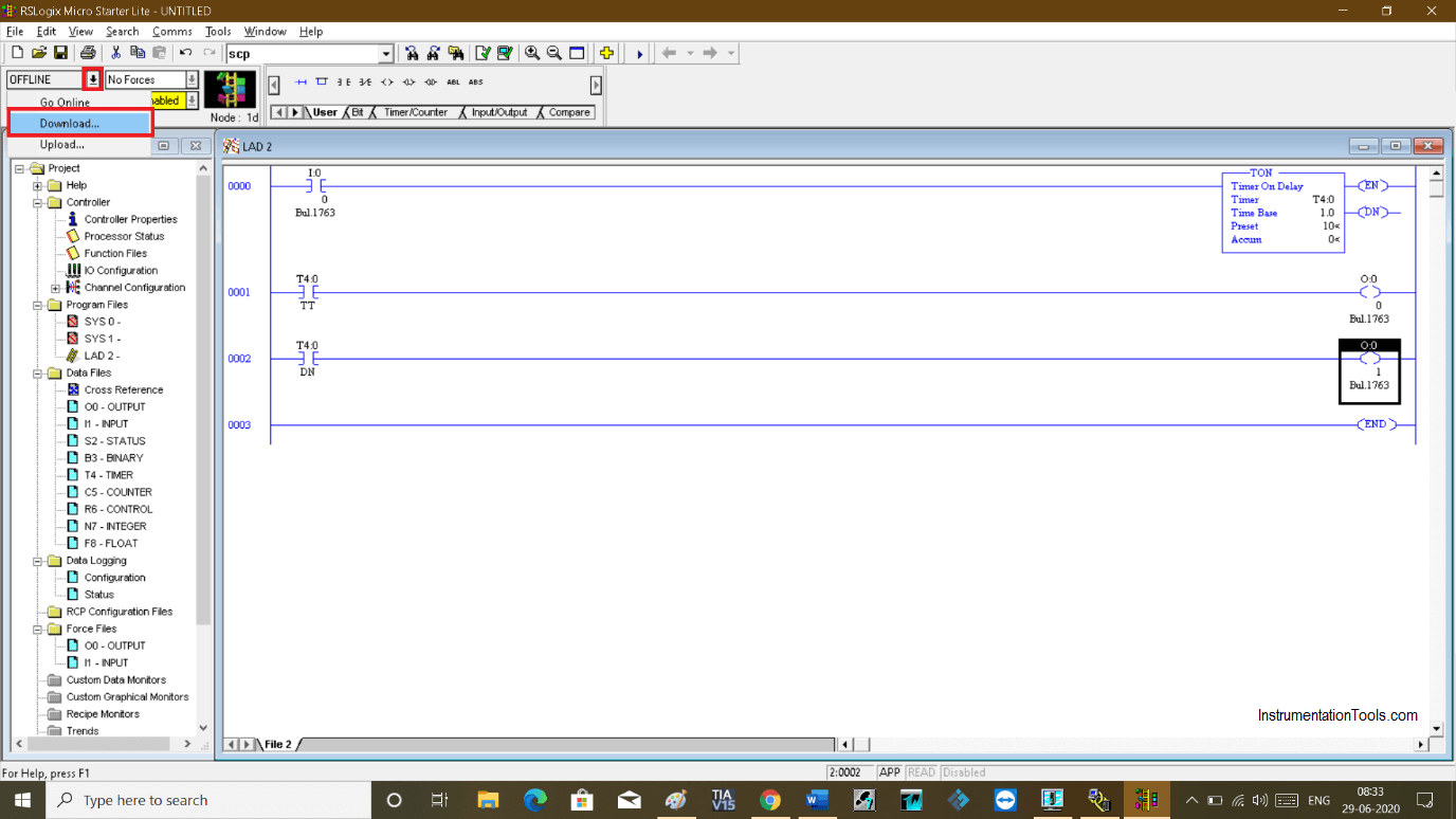
Allen Bradley RsLogix Emulator

Step 8:

Now, click on the drop-down menu on the top left side. Click on the “download” option.

Clicking on the download option will generate several pop-ups. Click “yes” on each pop-up you receive.

Rslogix 500 emulator tutorial

Step 9:

After downloading, click on “go online” from the same drop-down as shown in the above window.
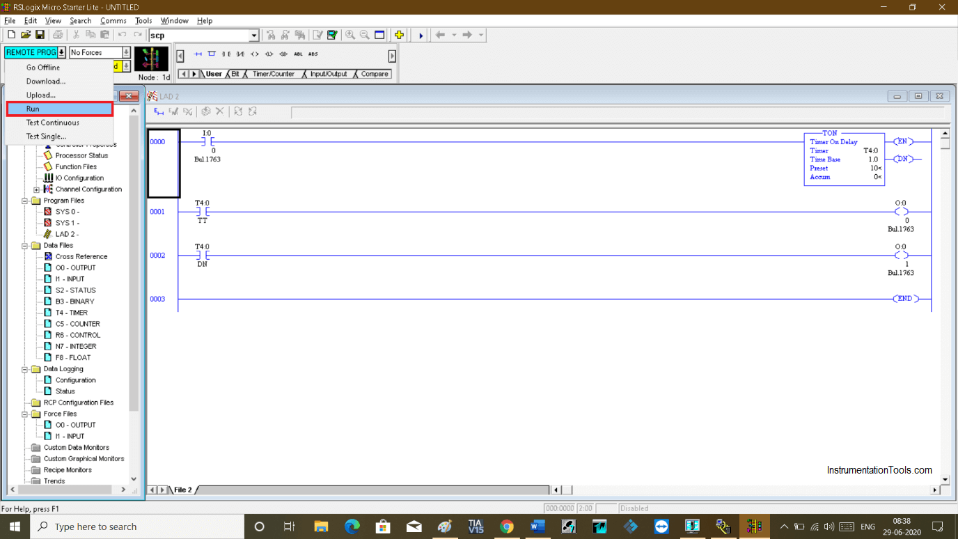
Go online in RsLogix

Step 10:

Again from the same drop-down menu choose “run” to test the logic.
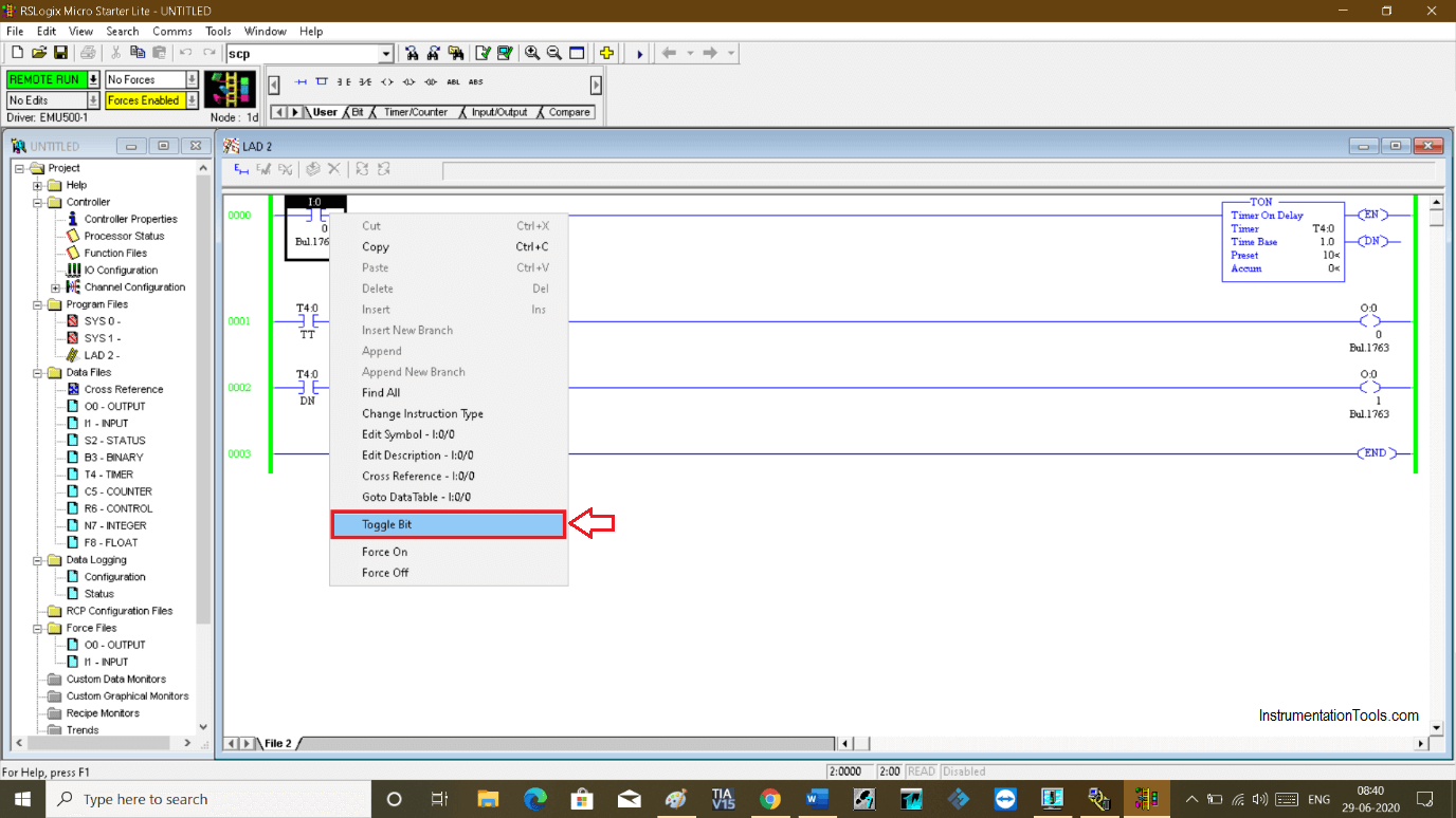
RsLogix Run

Step 11:

To test the logic, select input and do right-click and select “toggle bit” to turn input ON.
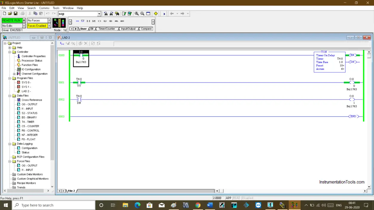
PLC Toggle Bit

Step 12:

While the timer is timing 1st output is ON.
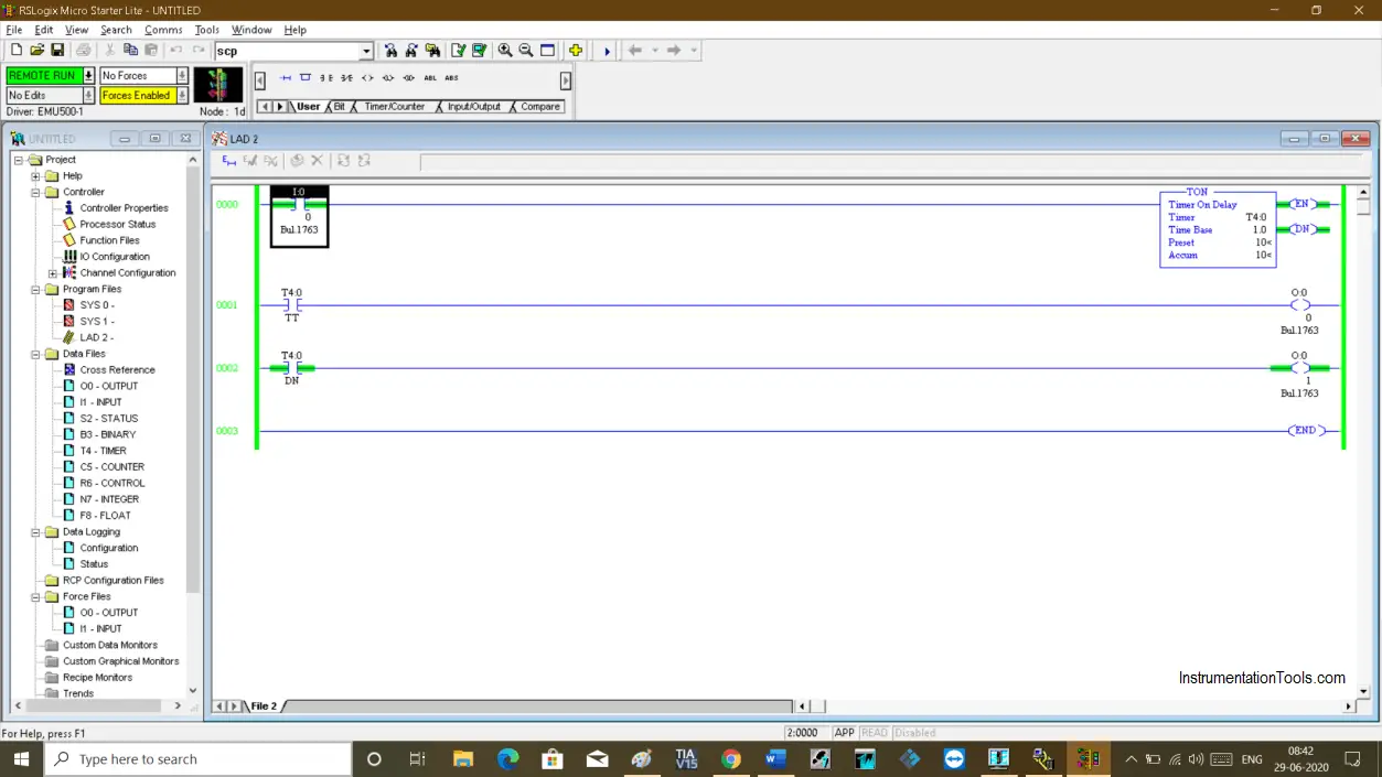
Emulator in Allen Bradley RsLogix

Step 13:

After the timer completes its timing 2nd output will energize.

Using RSLogix Emulator in a Project

Author: Suhel Patel

If you liked this article, then please subscribe to our YouTube Channel for PLC and SCADA video tutorials.

You can also follow us on Facebook and Twitter to receive daily updates.

Read Next:

  • PLC Alarm Acknowledge
  • Allen Bradley Powerflex VFD
  • How to Use Multimeter?
  • The script in Intouch Scada
  • Scaling for Analog Input
Don't Miss Our Updates
Be the first to get exclusive content straight to your email.
We promise not to spam you. You can unsubscribe at any time.
Invalid email address
You've successfully subscribed !

Continue Reading

Create User-Defined Data Types and Function Blocks in Studio 5000
Redundant Automation Systems – Need and Advantages
How to Create Project in Wonderware Intouch?
#6 PLC Best Practices – Validate Timers and Counters
Draw a Ladder Logic to switch ON-OFF a Bulb using a Toggle Switch ?
Peripheral Inputs and Outputs in Siemens PLC
Share This Article
Facebook Whatsapp Whatsapp LinkedIn Copy Link
Share
Leave a Comment

Leave a Reply Cancel reply

Your email address will not be published. Required fields are marked *

Stay Connected

128.3kFollowersLike
69.1kFollowersFollow
210kSubscribersSubscribe
38kFollowersFollow

Categories

Explore More

PLC Program for Blinking Lamp on 5 Seconds Interval
STAR-DELTA Auto And Manual Program using XG5000 Software
How to Use Encode and Decode Instructions in PLC ?
Concept of DCS in Industrial Automation
Types of SCADA System Architecture
Real-Time Clock in Omron PLC? – CX Programmer
How to Backup and Restore from Simatic Prosave HMI?
Use of Isolators and Barriers in Electrical Panel

Keep Learning

System Architecture in Industrial Automation

How to Design a System Architecture in Industrial Automation?

OMRON PLC program for waste-burning automation

Waste-Burning System OMRON PLC Program Example

Door Locking System - PLC Applications Examples

Door Locking System – PLC Applications Examples

Conveyor Control with Main Motor and Backup Motor

Conveyor Operation with a Backup Motor using PLC Ladder Diagram

CPU Communication Ports in Siemens PLC

Types of CPU Communication Ports in Siemens PLC

What is the consumed tag in Studio 5000 software?

Produced Tags and Consumed Tags in Studio 5000

Pneumatic valve operation in sequence mode

Sequential PLC Programming for the Pneumatic Valves

Function Block Diagram - Studio 5000 Logix Designer

Define the Order of Execution in Functional Block Diagram of Studio 5000

Learn More

Gas Turbine Interview Questions and Answers

Gas Turbine Interview Questions and Answers

Control Valve pressure recovery

What is Control Valve Flashing ?

Vacuum Circuit Breaker Principle

What is Vacuum Circuit Breaker?

Power Electronics Objective Questions

Chopper Control Strategies Objective Questions

Measure AC Voltage using Multimeter

How to Measure AC Voltage using Multimeter

PLC Program for Sequential Motor Control

PLC Program for Sequential Motor Control

Instrumentation Deliverables Generated from 3D Modeling

Instrumentation Deliverables Generated from 3D Modeling

Solenoid-controlled Valve Problem

Solenoid-controlled Valve Problem

Menu

  • About
  • Privacy Policy
  • Copyright

Quick Links

  • Learn PLC
  • Helping Hand
  • Part Time Job

YouTube Subscribe

Follow US
All rights reserved. Reproduction in whole or in part without written permission is prohibited.
Welcome Back!

Sign in to your account

Username or Email Address
Password

Lost your password?