Inst ToolsInst ToolsInst Tools
  • Courses
  • Automation
    • PLC
    • Control System
    • Safety System
    • Communication
    • Fire & Gas System
  • Instrumentation
    • Design
    • Pressure
    • Temperature
    • Flow
    • Level
    • Vibration
    • Analyzer
    • Control Valve
    • Switch
    • Calibration
    • Erection & Commissioning
  • Interview
    • Instrumentation
    • Electrical
    • Electronics
    • Practical
  • Q&A
    • Instrumentation
    • Control System
    • Electrical
    • Electronics
    • Analog Electronics
    • Digital Electronics
    • Power Electronics
    • Microprocessor
  • Request
Search
  • Books
  • Software
  • Projects
  • Process
  • Tools
  • Basics
  • Formula
  • Power Plant
  • Root Cause Analysis
  • Electrical Basics
  • Animation
  • Standards
  • 4-20 mA Course
  • Siemens PLC Course
Reading: Moving Iron Vane Meter Movement
Share
Font ResizerAa
Inst ToolsInst Tools
Font ResizerAa
  • Courses
  • Design
  • PLC
  • Interview
  • Control System
Search
  • Courses
  • Automation
    • PLC
    • Control System
    • Safety System
    • Communication
    • Fire & Gas System
  • Instrumentation
    • Design
    • Pressure
    • Temperature
    • Flow
    • Level
    • Vibration
    • Analyzer
    • Control Valve
    • Switch
    • Calibration
    • Erection & Commissioning
  • Interview
    • Instrumentation
    • Electrical
    • Electronics
    • Practical
  • Q&A
    • Instrumentation
    • Control System
    • Electrical
    • Electronics
    • Analog Electronics
    • Digital Electronics
    • Power Electronics
    • Microprocessor
  • Request
Follow US
All rights reserved. Reproduction in whole or in part without written permission is prohibited.
Inst Tools > Blog > Electrical Theory > Moving Iron Vane Meter Movement

Moving Iron Vane Meter Movement

Last updated: August 7, 2018 5:53 pm
Editorial Staff
Electrical Theory
No Comments
Share
2 Min Read
SHARE

The moving iron vane movement (Figure 1) can be used to measure both AC current and voltage. By changing the meter scale calibration, the movement can be used to measure DC current and voltage. The moving iron vane meter operates on the principle of magnetic repulsion between like poles.

The measured current flows through a field coil which produces a magnetic field proportional to the magnitude of current. Suspended in this field are two iron vanes attached to a pointer.

Moving Iron Vane Meter Movement

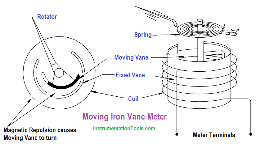
Figure 1 : Moving Iron Vane Meter Movement

The two iron vanes consist of one fixed and one movable vane. The magnetic field produced by the current flow magnetizes the two iron vanes with the same polarity regardless of the direction of current through the coil. Since like poles repel one another, the moving iron vane pulls away from the fixed vane and moves the meter pointer.

This motion exerts a force against a spring. The distance the moving iron vane will travel against the spring depends on the strength of the magnetic field. The strength of the magnetic field depends on the magnitude of current flow.

As stated previously, this type of meter movement may also be used to measure voltage. When this type of movement is used to measure voltage, the field coil consists of many turns of fine wire used to generate a strong magnetic field with only a small current flow.

Don't Miss Our Updates
Be the first to get exclusive content straight to your email.
We promise not to spam you. You can unsubscribe at any time.
Invalid email address
You've successfully subscribed !

Continue Reading

DC Generator Theory
Low Voltage Protection (LVP) and Low Voltage Release (LVR)
Applying Kirchhoff’s Current Law
Battery Hazards
Synchronous Motors
DC Motor Theory
Share This Article
Facebook Whatsapp Whatsapp LinkedIn Copy Link
Share
Leave a Comment

Leave a Reply Cancel reply

Your email address will not be published. Required fields are marked *

Stay Connected

128.3kFollowersLike
69.1kFollowersFollow
210kSubscribersSubscribe
38kFollowersFollow

Categories

Explore More

Calculate Power in Series RC Circuit
Series and Parallel Inductors
AC Generator Parts
Apparent Power, True Power, Reactive Power & Total Power
Induction Motor
Inductance and Inductive Reactance
Thermocouples
Transformer Efficiency

Keep Learning

Chemical Battery

Batteries

Series-Wound DC Generator Principle

Series-Wound DC Generators

Voltage Polarities

Voltage Polarity and Current Direction

Power Triangle

Power Triangle

Thermoelectricity principle

Methods of Producing Voltage (Electricity)

DC Motor Action

DC Motor Speed

AC Generator Operation

AC Generator Theory

Calculate Power in Series RCL Circuit

Calculate Power in Series RCL Circuit

Learn More

Core-Type Transformer

Transformer Theory of Operation

Hydrostatic interface level measurement Formula

Hydrostatic Interface Level Measurement

Hydraulic Actuator Principle

What is a Hydraulic Actuator ?

Transformers Coolers Weld Joints Oil

Transformers Coolers Weld Joints Oil Oozes Were Eye Sores

Online PLC Ladder Logic

Mis-conceptions of PLC Ladder Logic

Types of Instructions in PLC Programming

Types of Instructions in PLC Programming

Organization block Siemens

Tia Portal – OB30 Cyclic Interrupt Organization Block

Time Response Analysis

Steady-state Errors & Error Constants

Menu

  • About
  • Privacy Policy
  • Copyright

Quick Links

  • Learn PLC
  • Helping Hand
  • Part Time Job

YouTube Subscribe

Follow US
All rights reserved. Reproduction in whole or in part without written permission is prohibited.
Welcome Back!

Sign in to your account

Username or Email Address
Password

Lost your password?