Inst ToolsInst ToolsInst Tools
  • Courses
  • Automation
    • PLC
    • Control System
    • Safety System
    • Communication
    • Fire & Gas System
  • Instrumentation
    • Design
    • Pressure
    • Temperature
    • Flow
    • Level
    • Vibration
    • Analyzer
    • Control Valve
    • Switch
    • Calibration
    • Erection & Commissioning
  • Interview
    • Instrumentation
    • Electrical
    • Electronics
    • Practical
  • Q&A
    • Instrumentation
    • Control System
    • Electrical
    • Electronics
    • Analog Electronics
    • Digital Electronics
    • Power Electronics
    • Microprocessor
  • Request
Search
  • Books
  • Software
  • Projects
  • Process
  • Tools
  • Basics
  • Formula
  • Power Plant
  • Root Cause Analysis
  • Electrical Basics
  • Animation
  • Standards
  • 4-20 mA Course
  • Siemens PLC Course
Reading: P&ID Guidelines for Pumps Heat Exchangers
Share
Notification Show More
Font ResizerAa
Inst ToolsInst Tools
Font ResizerAa
  • Courses
  • Design
  • PLC
  • Interview
  • Control System
Search
  • Courses
  • Automation
    • PLC
    • Control System
    • Safety System
    • Communication
    • Fire & Gas System
  • Instrumentation
    • Design
    • Pressure
    • Temperature
    • Flow
    • Level
    • Vibration
    • Analyzer
    • Control Valve
    • Switch
    • Calibration
    • Erection & Commissioning
  • Interview
    • Instrumentation
    • Electrical
    • Electronics
    • Practical
  • Q&A
    • Instrumentation
    • Control System
    • Electrical
    • Electronics
    • Analog Electronics
    • Digital Electronics
    • Power Electronics
    • Microprocessor
  • Request
Follow US
All rights reserved. Reproduction in whole or in part without written permission is prohibited.
Inst Tools > Blog > Erection & Commissioning > P&ID Guidelines for Pumps Heat Exchangers

P&ID Guidelines for Pumps Heat Exchangers

Last updated: September 29, 2016 3:08 pm
Editorial Staff
Erection & Commissioning
No Comments
Share
3 Min Read
SHARE

P&ID Guidelines for Pumps Heat Exchangers

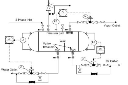
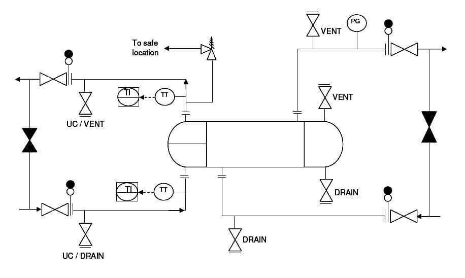
  1. Proper equipment symbol should be selected first of all, as shown in the presented drawing. This should be selected from the list of equipment symbols on the legend sheets of a particular project.
  2. All the nozzles on the exchanger should then be correctly represented with size and flanges. This includes inlet and outlet nozzles, drains, vents, utility connections etc.
  3. Inlet and outlet lines are the next to be drawn up. Line number, material class, size etc. is to be correctly assigned to each of the lines. If the unit is envisaged to be in operation while the exchanger is under maintenance, then bypass lines should be drawn up on shellside, tubeside or on both sides as shown in the drawing presented here.
  4. Isolation valves, spectacle blinds, spacers etc. to be used for maintenance should be drawn up next on the inlet / outlet lines. Bypass lines to be fitted with normally closed isolation valves.
  5. Thermal relief valve should be provided where required. Generally thermal relief valves are required on the cold liquid streams, when there is a possibility of blockage in the heating medium on the other side of exchanger. In case of such blockage, there is possibility of overheating the cold stream and hence requirement for thermal relief valve. Discharge of a relief valve to be routed to an appropriate, safe location.
  6. Drains and vents to be provided on both sides of the exchanger (hot and cold sides), either on the exchanger itself or inlet / outlet piping, so that the equipment can be completely drained for maintenance.
  7. For fouling service on the tubeside, utility connections should be provided as indicated in the presented drawing, for cleaning purpose.
  8. Temperature and pressure gauges and transmitters to be provided as per requirements for operating and controlling the equipment. Normally temperature monitoring is required for the process side of the heat exchanger. Also generally temperature control is implemented on the process side of the exchanger.
  9. All the guidelines given here are very general and may be modified as per specific requirements of any particular project.
Don't Miss Our Updates
Be the first to get exclusive content straight to your email.
We promise not to spam you. You can unsubscribe at any time.
Invalid email address
You've successfully subscribed !

Continue Reading

Impulse Tubing Leak Test Checks
How to Install Thermowell on an Elbow?
How Not to Install an Instrument and Wrong Practices
Pressure Transmitters Installation Tips
Commissioning a Differential Pressure Transmitter in a Pressurized Boiler Steam Drum
Cut-outs between Platforms or Grating for Field Instruments
Share This Article
Facebook Whatsapp Whatsapp LinkedIn Copy Link
Share
Leave a Comment

Leave a Reply Cancel reply

Your email address will not be published. Required fields are marked *

Stay Connected

128.3kFollowersLike
69.1kFollowersFollow
210kSubscribersSubscribe
38kFollowersFollow

Categories

Explore More

Installation & Commissioning Tips for HART Devices
Installation and Calibration of Pressure Transmitter
Magnetic Float Level Switch Installation Techniques
Thermocouple Temperature Measurement Errors
Instrument Tube Fitting Installation – Part 1
Magnetic Flow Meters Installation Guidelines
Instrument Tube Fitting Installation – Part 2
What are the Mounting Techniques of Diaphragm Seals?

Keep Learning

What is FAT and SAT?

What is FAT and SAT? Difference between them

Hook-up Diagram for Pressure Gauge

What is Instrument Hook Up Diagram ?

What is Instrument Air Manifold

What is Instrument Air Manifold ?

Multiple Thermowell Installations Problems

Multiple Thermowell Installations Problems

Gas Detectors Location Installation

Gas Detectors Installation Techniques

P&ID Guidelines for Centrifugal Compressor Systems

P&ID Guidelines for Centrifugal Compressor Systems

Pipeline Project Management

Pipeline Project Management

Piping and Instrumentation Diagram

What is Piping and Instrumentation Diagram (P&ID) ?

Learn More

Electrical Machines Questions and Answers

Synchronous Machine Quiz

Series - Wound DC Motor

Series-Wound Motor

HVAC Questions & Answers

HVAC Questions & Answers

RF-Capacitance Level Switch Principle

RF Capacitance Level Switch Working Principle

Single-beam non-dispersive analyzer

Single-beam Non-dispersive Analyzer

How to Calculate Network Speed?

Factors to Consider When Calculating Network Speed

HVDC transmission compared to HVAC transmission

Comparison of HVDC transmission and HVAC transmission

LVDT-Operation-Principle-Animation

LVDT Working Principle Animation

Menu

  • About
  • Privacy Policy
  • Copyright

Quick Links

  • Learn PLC
  • Helping Hand
  • Part Time Job

YouTube Subscribe

Follow US
All rights reserved. Reproduction in whole or in part without written permission is prohibited.
Welcome Back!

Sign in to your account

Username or Email Address
Password

Lost your password?