Vortex Meters can be used for a wide range of fluids, i.e. liquids, gases, and steam. They are to be seen as the first choice, subject to verification to cover the requirements of a particular application.
Vortex meters are essentially frequency meters since they measure the frequency of vortices generated by a “bluff body” or”shedder bar”.
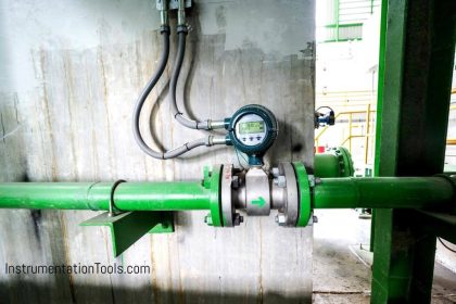
Vortex Flow Meter

Vortices will only occur from a certain velocity (Re-number) on-wards, consequently, vortex meters will have an elevated zero referred to as the “cut-off” point. Before the velocity becomes nil, the meter output will be cut to zero.
At a certain back-flow (above cut-off point) some vortex meters could produce an output signal, which could lead to a false interpretation.
Also See: Vortex Flow Meter Animation
Vortex meters are actual volume flow meters, like orifice meters. These intrusive meters like orifice meters, will cause the pressure to drop as flow is increased, resulting in a permanent loss. consequently, liquids near their boiling point could introduce cavitation as the pressure across the meter drops below the vapor pressure of the liquid.
As soon as the pressure recovers above the vapour pressure the bubbles will impode. cavitation causes the meter to malfunction and should be avoided at all times.
Vortex Flow Meter Principle
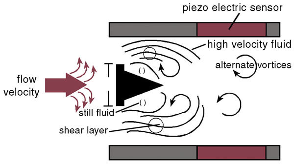
A fluid flowing with a certain velocity and passing a fixed obstruction generates vortices. The generation of vortices is known as Karman’s Vortices and the culmination point of vortices will be approx. 1.2D downstream of the bluff body.

Strouhal discovered that as soon as a stretched wire starts vibrating in an air flow, the frequency will be directly proportional to air velocity,
St= f*d/V0 (without dimension)
St= Strouhal’s number
f=frequency of wire
d=diameter of wire
V0= Velocity
This phenomenon is called “vortex shedding” and the train of vortices is known as “Karman’s Vortex Street”.
The frequency of vortex shedding is a direct linear function of fluid velocity and frequency depends upon the shape and face width of the bluff body. Since the width of the obstruction and inner diameter of the pipe will be more or less constant, the frequency is given by the expression-
f=(St*V)/c*D
f= vortex frequency, Hz
St=strouhal’s number, dimension less
V=Fluid velocity at the shedder bar, m/s
D=Inner diameter of the pipe, m
c=constant (ratio d/D)
d= Face width of shedder bar, m
The pressure loss gradient across the vortex meter will have a similar shape to that of an orifice meter. the lowest point in pressure will be at the sheddar bar (comparable to vena contracta for the orifice meter). downstream of this point of pressure will recover gradually, finally resulting in permanent pressure loss. To avoid cavitation, the pressure loss at vena-contracta is of interest.
The minimum back pressure required to ensure cavitation doesn’t occur is:
Pmin=3.2*Pdel + 1.25*Pv
Pmin= minimum required pressure at five pipe diameters downstream of the flow meter in bar
Pdel= calculated permanent pressure loss in bar
Pv= vapour pressure at operating temperature in bar
Remember- for most vortex meters d/D will have a range, of 0.22 – 0.26, & frequency of vortices will depend on the size of the meter, larger the meter, the lower the frequency. So the maximum diameter of the vortex meter is restricted because the resolution of the meter could become a problem for control purposes.
To overcome this problem, on-board digital multipliers are used which will multiply the vortex frequency without additional error.
Frequency Sensing Principle
Piezo-electrical Sensors- a pair of piezo-electrical crystals are built into the shedder bar. as the shedder bar will be subject to alternating forces caused by shedding frequency, so will the piezo-crystals.
Variable capacitance Sensors- a pair of variable capacitance sensors is built into the sheddar bar. As the shedder bar will be subject to alternating micro-movements caused by forces as a result of the shedding frequency, the capacitors will change their capacitance accordingly.
The performance of Vortex meters is influenced by
- change in shedder bar geometry owning to erosion
- change in shedder bar geometry owning to deposits, i.e. Wax
- corrosion of upstream piping
- change in position of shedder bar if not properly secured
- Hydraulic noise.
The general vortex meter will consist of the following electronic parts-
- pick-up elements,
- AC-pre amplifiers,
- AC-amplifier with filters,
- Noise abatement features,
- Schmitt Trigger,
- Microprocessor
Features
The vortex shedding meter provides a linear digital (or analog) output signal without the use of separate transmitters or converters, simplifying equipment installation. Meter accuracy is good over a potentially wide flow range, although this range is dependent upon operating conditions.
The shedding frequency is a function of the dimensions of the bluff body and, being a natural phenomenon ensures good long-term stability of calibration and repeatability of better than ±0.15% of the rate. There is no drift because this is a frequency system.
The meter does have any moving or wearing components, providing improved reliability and reduced maintenance. Maintenance is further reduced by the fact that there are no valves or manifolds to cause leakage problems. The absence of valves or manifolds results in a particularly safe installation, an important consideration when the process fluid is hazardous or toxic.
If the sensor utilized is sufficiently sensitive, the same vortex-shedding meter can be used on both gas and liquid. In addition, the calibration of the meter is virtually independent of the operating conditions (viscosity, density, pressure, temperature, and so on) whether the meter is being used on gas or liquid.
The vortex shedding meter also offers a low installed cost, particularly in pipe sizes below 6 in. (152 mm) diameter, which compares competitively with the installed cost of an orifice plate and differential pressure transmitter.
The limitation includes the meter size range. Meters below 0.5 in. (12 mm) diameter are not practical, and meters above 12 in. (300 mm) have limited application due to their high cost compared to an orifice system and their limited output pulse resolution.
The number of pulses generated per unit volume decreases on a cube law with increasing pipe diameter. Consequently, a 24 in. (610 mm) diameter vortex shedding meter with a typical blockage ratio of 0.3 would only have a full-scale frequency output of approximately 5 Hz at 10 ft/s (3 m/s) fluid velocity.
Selection and Sizing
As the first step in the selection process, the operating conditions (process fluid temperature, ambient temperature, line pressure, and so on) should be compared with the meter specification.
The meter-wetted materials (including bonding agents) and sensors should then be checked for compatibility with the process fluid both with regard to chemical attack and safety. On oxygen, for example, non-ferrous material should be avoided or approached with extreme caution. The meter minimum and maximum flow rates for the given application should then be established.
The meter minimum flow rate is established by a Reynolds number of 10,000 to 10,500, the fluid density, and a minimum acceptable shedding frequency for the electronics. The maximum flow rate is governed by the meter pressure loss (typically two velocity heads), the onset of cavitation with liquids, and sonic velocity flow (choking) with gases.
Consequently, the flow range for any application depends totally upon the operating fluid viscosity, density, and vapor pressure, and the application’s maximum flow rate and line pressure.
On low-viscosity products such as water, gasoline, and liquid ammonia, and with an application maximum velocity of 15 ft/s (4.6 m/s), vortex-shedding meters can have a rangeability of about 20:1 with a pressure loss of approximately 4 PSIG (27.4 kPa).
The meter’s good (“of rate”) accuracy and digital linear output signal make its application over wide flow ranges a practical proposition. The rangeability declines proportionally with the increase in viscosity, decrease in density, or reduction in the maximum flow velocity of the process. Vortex shedding meters are therefore unsuitable for use on high-viscosity liquids.
Vortex Meter Advantages
- Vortex meters can be used for liquids, gases, and steam
- Low wear (relative to turbine flow meters)
- Relatively low cost of installation and maintenance
- Low sensitivity to variations in process conditions
- Stable long-term accuracy and repeatability
- Applicable to a wide range of process temperatures
- Available for a wide variety of pipe sizes
Vortex Flow Meter Limitations
- Not suitable for very low flow rates
- A minimum length of straight pipe is required upstream and downstream of the vortex meter
Vortex Flow Meter Applications
Vortex flow meters are suitable for a variety of applications and industries but work best with clean, low-viscosity, medium to high-speed fluids.
Some of the main uses include:
- Custody transfer of natural gas metering
- Steam measurement
- The flow of liquid suspensions
- General water applications
- Liquid chemicals & pharmaceuticals
If you liked this article, then please subscribe to our YouTube Channel for Instrumentation, Electrical, PLC, and SCADA video tutorials.
You can also follow us on Facebook and Twitter to receive daily updates.
Read Next:
- Advantages of All Flow Meters
- Orifice Plate Flow Requirements
- Selection Parameters of Rotameter
- Animation of Vortex Flowmeter
- Turbine Flow Meter Working Principle


Lovely animations to explain working principles of instruments
The article is very good as I was referring Liptak from where few portions of the article is taken , the animations made the things more clearer. Great work.
is this application available in IOS?
As on Date only Android. You can visit InstrumentationTools.com website directly.
Sir, i have got a question we are working on a revamp project. so there was an existing vortex flow meter of 16″. now the line size has been increased to 20″ . is it possible to use the existing vortex flow meter on that line.
It depends on the flow rate, working pressure.
if you still have a problem , you can contact us for information info@bcstgroup.com, http://www.bcstgroup.com
Thanks
Which Will show higher flow results, vortex flow meter with a constant density, or multivariable vortex flow meter?
The constant density is at 340oC, pressure 45bar. Actual steam condition is 250oC and 40bar.
which flow meter suitable for argon gas measurement and argon and co2 mixture gas flow measurement ?