Swirl flow meters combine the advantages of turbine and vortex flow meter technologies. They have a high turndown ratio and high accuracy (turbine).
They are highly reliable, robust, and maintenance-free (vortex)
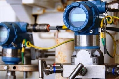
Swirl Flow Meters

Swirl Flow Meter Principle
A turbine-shaped inlet section forces the axial flow entering the flow meter into a rotational movement. A vortex core forms in the center of the primary rotation. A secondary rotation forms in the vortex core producing thread-like spirals.
The frequency of this secondary rotation is linearly proportional to the flow rate over a wide Reynolds Number range. Pressure variations resulting from the secondary rotation are detected by a piezo sensor and converted into electrical pulses.
These pulses are processed in the DSP converter into scaled analog and digital signals which display the measured flow value.
Why Swirl Flow Meter is Advantage?
The swirl flow meter advances vortex flow technology by improving accuracy, simplifying installation, increasing turndown, and reducing the cost of ownership.
Swirl meters operate on similar vortex flow meter principles, but have certain advantages.
- Swirl meters create their own flow profile within the meter, so they require only three straight pipe diameters upstream and one downstream. Vortex meters typically require a minimum of 15 diameters upstream and five downstream to develop a proper flow profile for accurate measurements. So the swirl flow meter better fits applications with tight piping requirements.
- When applying vortex meters, the user typically chooses a flow meter reduced by one or two pipe sizes from the process pipeline size. This ensures that the flow meter experiences the higher velocities required across the desired flow range, but adds piping reduction and expansion costs. Swirl meters require lower flow velocities for proper operation, and so usually may be sized the same as the process pipe size.
- Swirl meters have a turndown ratio of up to 30:1, while most vortex meters are limited to 20:1 turndown ratios. Additionally, swirl meters can perform to viscosities of up to 30 cp while vortex meters are generally limited to 8-10 cp maximum.
- Swirl meters offer a higher degree of accuracy, up to 0.5% better than most vortex meters in gas applications.

For these reasons, swirl flow meters have been gaining ground on vortex flow meters and are currently experiencing growth.
The swirl meter operates under the same technology as the vortex flow meter. It takes advantage of vortex shedding principles that occur when a flowing fluid comes up against a bluff obstacle in its path. Additionally, the swirl meter adds a “twist” in conditioning the fluid, which results in the reduced installation considerations mentioned above, while improving performance.
The swirl meter forces incoming fluid through a fixed swirl-inducing element located at the upstream inlet of the meter body. The “swirler” imparts a tangential velocity to the fluid, and then accelerates the flow via a reduction in the meter body bore.
The primary fluid rotation caused by the swirler has at its core a low-pressure zone. This low-pressure zone is thrown into a secondary rotation proportional to the flow rate. The same piezoelectric sensor as used in vortex meters measures the frequency of this phenomenon at the point of maximum fluid velocity.
An increase in the meter’s bore as the fluid approaches the meter outlet decelerates the fluid to its original velocity. A “deswirler” welded to the meter body near the outlet eliminates the tangential velocity imparted to the fluid at the inlet. This avoids affecting operation of other downstream instrumentation.
Limitations of Swirl Flow Meters
While both swirl and vortex shedders offer a wide measurement range, they cannot measure fluid flows down to a true zero. Some minimal fluid velocity must be present to act upon the piezoelectric sensing element.
So these meters may not register low levels of fluid movement in the pipeline. For this reason swirl and vortex meters are not readily suitable to batch processing with start and stop flow actions. In some cases continuous flow with a diverter can overcome this consideration
Both swirl and vortex meters are also susceptible to external interference such as pipe vibration, EMF, and hydraulic noise. Interference occurs if these disturbances are within the frequency range of the meter and of higher amplitude than the flow signal itself. The meter may confuse the disturbance with a flow signal, reporting a false flow rate.
The sophisticated digital signal processing can filter these conditions, but the best cure is to treat the root cause of the interference by removing the disturbing influence. So when such disturbances arise, users should check into piping vibration, anchoring, location, and proximity to electrical devices.
Typical Applications of Swirl and Vortex Flow Meters

If you liked this article, then please subscribe to our YouTube Channel for Instrumentation, Electrical, PLC, and SCADA video tutorials.
You can also follow us on Facebook and Twitter to receive daily updates.
Read Next:
- Target Flow Meter Principle
- Flow measurement Theory
- What is the Flow Meter K-factor
- Orifice Plate Pressure Tap
- Vortex Meter Animation