The FF standard specifies many different function blocks for the construction of control algorithms. Ten of them are considered “basic” FF function blocks:
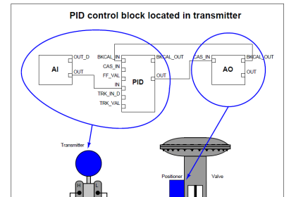
- AI – Analog Input
- AO – Analog Output
- B – Bias
- CS – Control Selector
- DI – Discrete Input
- DO – Discrete Output
- ML – Manual Loader
- PD – Proportional/Derivative control
- PID – Proportional/Integral/Derivative control
- RA – Ratio
Nineteen more “Advanced” function blocks are incorporated in the FF standard:
- Pulse Input
- Complex Analog Output
- Complex Discrete Output
- Step Output PID
- Device Control
- Setpoint Ramp
- Splitter
- Input Selector
- Signal Characterizer
- Dead Time
- Calculate
- Lead/Lag
- Arithmetic
- Integrator
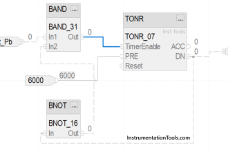
- Timer
- Analog Alarm
- Discrete Alarm
- Analog Human Interface
- Discrete Human Interface
Five more function blocks are specified as well:
- Multiple Analog Input
- Multiple Analog Output
- Multiple Digital Input
- Multiple Digital Output
- Flexible Function Block
The primary benefit of standardization is that the end-user may choose FF instruments manufactured by any standard-compliant vendor, and those function blocks should behave the same as the equivalent function blocks within any other manufacturer’s model of FF device. There are, of course, examples where manufacturers have equipped their FF devices with “extended” capability function blocks going beyond the Fieldbus Foundation standard, and the user must beware of this.
Device-specific Function blocks
In addition to the function blocks necessary to construct control schemes, all FF instruments contain one Resource block and usually one or more Transducer blocks describing details specific to that instrument. The following computer screenshot shows all function blocks within a Rosemount model 3095MV Fieldbus transmitter:
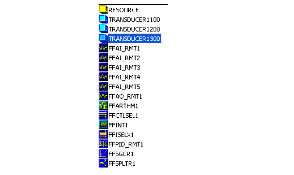
The Resource block appears first in this list, followed by three transducer blocks, then followed by the palette of general function blocks for use in constructing control algorithms. Information contained in the Resource block of an FF instrument includes the following:
- Identifier (the 32-byte code unique to every FF device)
- Type of device
- Device revision level
- Memory total and available (free) capacity
- Computation time
- Available features listing
- Current device state (Initializing, Standby, On-line, Failed, etc.)
Transducer blocks provide a means of organizing data relevant to the actual sensing inputs, outputs, calculated variables, and graphic displays of a FF device. There need not be a one-to one correspondence between the number of transducer blocks in an FF device and the number of physical I/O channels it has. For example, in the Rosemount 3095MV multivariable transmitter, transducer block 1100 manages all physical measurement inputs (pressure and temperature sensors) while transducer block 1200 is reserved for inferred mass flow (based on calculations performed on the raw sensor measurements) and transducer block 1300 manages data for the liquid crystal display (LCD).