Inst ToolsInst ToolsInst Tools
  • Courses
  • Automation
    • PLC
    • Control System
    • Safety System
    • Communication
    • Fire & Gas System
  • Instrumentation
    • Design
    • Pressure
    • Temperature
    • Flow
    • Level
    • Vibration
    • Analyzer
    • Control Valve
    • Switch
    • Calibration
    • Erection & Commissioning
  • Interview
    • Instrumentation
    • Electrical
    • Electronics
    • Practical
  • Q&A
    • Instrumentation
    • Control System
    • Electrical
    • Electronics
    • Analog Electronics
    • Digital Electronics
    • Power Electronics
    • Microprocessor
  • Request
Search
  • Books
  • Software
  • Projects
  • Process
  • Tools
  • Basics
  • Formula
  • Power Plant
  • Root Cause Analysis
  • Electrical Basics
  • Animation
  • Standards
  • 4-20 mA Course
  • Siemens PLC Course
Reading: How can we use a DP Flow Transmitter for Level Measurement
Share
Notification Show More
Font ResizerAa
Inst ToolsInst Tools
Font ResizerAa
  • Courses
  • Design
  • PLC
  • Interview
  • Control System
Search
  • Courses
  • Automation
    • PLC
    • Control System
    • Safety System
    • Communication
    • Fire & Gas System
  • Instrumentation
    • Design
    • Pressure
    • Temperature
    • Flow
    • Level
    • Vibration
    • Analyzer
    • Control Valve
    • Switch
    • Calibration
    • Erection & Commissioning
  • Interview
    • Instrumentation
    • Electrical
    • Electronics
    • Practical
  • Q&A
    • Instrumentation
    • Control System
    • Electrical
    • Electronics
    • Analog Electronics
    • Digital Electronics
    • Power Electronics
    • Microprocessor
  • Request
Follow US
All rights reserved. Reproduction in whole or in part without written permission is prohibited.
Inst Tools > Blog > Guest Articles > How can we use a DP Flow Transmitter for Level Measurement

How can we use a DP Flow Transmitter for Level Measurement

Last updated: July 13, 2018 11:26 am
Editorial Staff
Guest Articles Level Measurement
2 Comments
Share
2 Min Read
SHARE

Firstly, I need to clarify, that a DP transmitter is not only used for measuring flow, as the user referred to in his question, to a DP flow transmitter.

A differential pressure transmitter (or DP cell) literally measures any differential pressure across its High and Low pressure measuring ports, and provides an output proportional to the difference in pressure between the High and Low pressure ports.

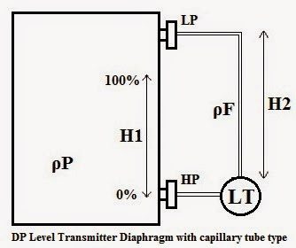
If you look at the mechanical hydraulic properties of a liquid inside a vessel, you will remember that the liquid exerts a specific pressure on the bottom of the vessel, based on the liquid level height (h=meters), the specific gravity (g=9.8 m/s), and the density (rho kg/m3) of the liquid.

The formula for calculating this pressure is P = rho x g x h.

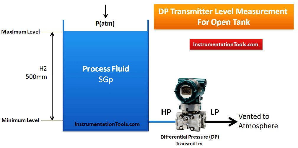
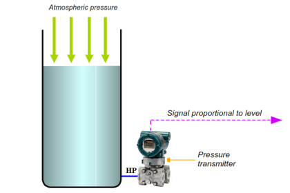
A DP cell can thus be used to measure the pressure of the liquid at the bottom of the vessel, and scaled to give a percentage level value proportional to the pressure measured.

In an open vessel scenario, a standard pressure transmitter can also be used.

Open Tank DP Level Measurement

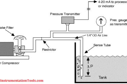
However, in a closed vessel, a DP cell must be used. The High pressure port measuring the bottom pressure of the liquid inside the vessel, and the Low pressure port, measuring the top pressure of the vessel to compensate for non-atmospheric pressures inside the sealed vessel.

DP Transmitter Level Measurement for Closed Tank Dry leg Method

Article by :
Ludwich Pretorius
Don't Miss Our Updates
Be the first to get exclusive content straight to your email.
We promise not to spam you. You can unsubscribe at any time.
Invalid email address
You've successfully subscribed !

Continue Reading

Displacer Level Transmitter Calibration using Water & Process Liquid
Differential Pressure Level Transmitter Errors
Internal Powered Modems
Point Level Detection Working Principle
Basics of DP Level Measurement
Radar Tank Gauging
Share This Article
Facebook Whatsapp Whatsapp LinkedIn Copy Link
Share
2 Comments
  • Sooraj says:
    July 19, 2018 at 4:45 pm

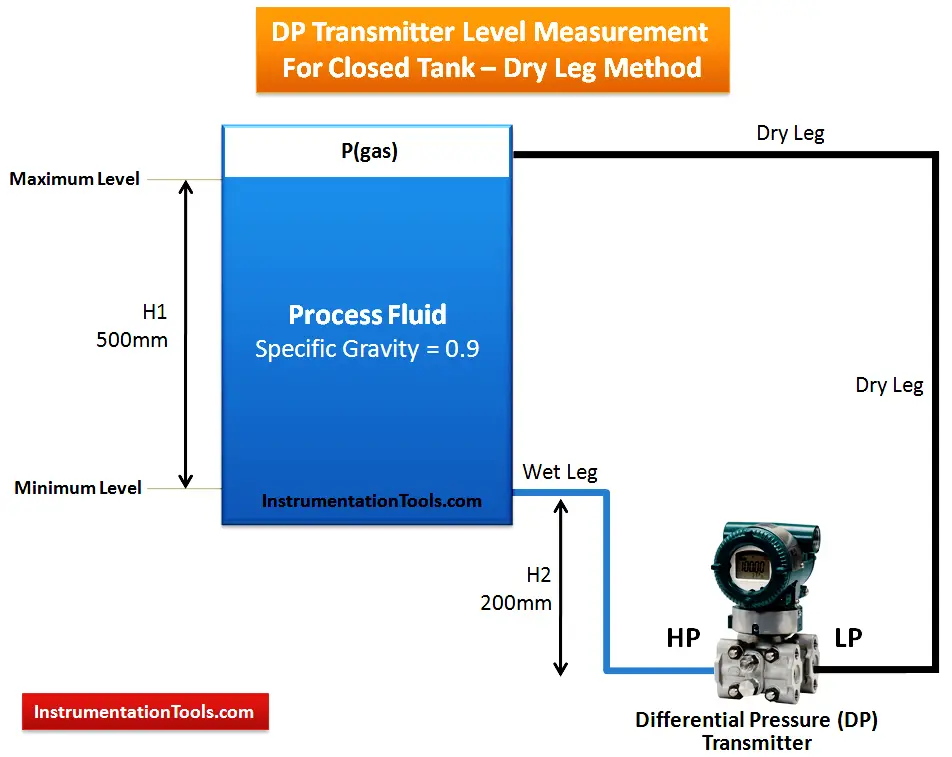
    Pls explain the level calculation when the transmitter is placed above the lower tapping and its a wet leg model.

    Reply
  • karthi says:
    February 12, 2019 at 12:52 pm

    hi

    i need now how to calcautaion in above dp tranmitter . can explanin with formula

    Reply

Leave a Reply Cancel reply

Your email address will not be published. Required fields are marked *

Stay Connected

128.3kFollowersLike
69.1kFollowersFollow
210kSubscribersSubscribe
38kFollowersFollow

Categories

Explore More

Closed tank DP Level Transmitter with wet leg Zero elevation Calibration
PLC System Documentation
Why You Need FDA Process Validation and How to Do It Right ?
The 5 ways Ultrasonic Sensors Work
Level Gauge Design
Displacer Level Transmitter Dry Calibration with Weights
Closed tank DP Level Transmitter with wet leg elevation zero direct mount Calibration
Displacer Level Measurement Calculations

Keep Learning

Density Measurement using Remote Seal Transmitters

Remote Seal Differential Pressure Transmitters Principle

Guided Wave Radar Questions and Answers

Guided Wave Radar Questions and Answers

Level Transmitters Auto Calibration

DP Level Transmitter Auto Calibration

Cable Glands

Using of MCT instead of Cable Glands on the Cabinets

Servo Level Transmitter Principle

Servo Level Transmitter Principle

Difference between Transparent Level Gauge and Reflex Level Gauge

Difference between Transparent Level Gauge and Reflex Level Gauge

PLC Program for Conditional Control Logic

PLC Program for Conditional Control Logic

Capillary Remote Seal Leave Measurement

Siemens Pressure Transmitter with Remote Seals Calculations

Learn More

PID Setup

PID in Studio 5000

Ethernet Questions and Answers

Ethernet Communication Interview Questions & Answers

DC Generator

DC Generator

Siemens TIA Portal Free Version Download

Siemens TIA Portal Free Version Download

input-output-relationships-of-transmitters

Input-Output Relationships of Transmitters

Centrifugal Compressor Shaft Vibrations Problem

Centrifugal Compressor near ½-RPM Frequency High Magnitude Shaft Vibrations

Chemical Dosing Control System

Introduction to Chemical Dosing System

Three Wire RTD Wheatstone bridge Circuit

RTD Wheatstone Bridge Circuits

Menu

  • About
  • Privacy Policy
  • Copyright

Quick Links

  • Learn PLC
  • Helping Hand
  • Part Time Job

YouTube Subscribe

Follow US
All rights reserved. Reproduction in whole or in part without written permission is prohibited.
Welcome Back!

Sign in to your account

Username or Email Address
Password

Lost your password?