Process Flow Diagram (PFD) is a drawing which essentially captures the process flow for a processing plant.
PFD is used to capture the main process equipment’s, main process stream, process/design conditions in these equipments and the basic process control scheme in a single drawing.
Entire process of a plant can be described using a few interconnected PFDs.
A PFD should normally contain the following information about the plant process.
- Main process equipment’s with reference tag numbers, name. Process operating and design conditions are also usually provided.
- Main process streams are normally provided with reference stream numbers. It should be noted that streams are different than lines and stream numbers are not related to line numbers in any way. The streams that normally do not have any flow are indicated with an abbreviation NNF (Normally No Flow).
- Basic process data for each stream is sometimes given in the PFD against each stream number. This includes data such as operating temperature, pressure, flowrates, compositions etc. for each process stream. Sometimes, this process data is represented for each stream number, in a separate drawing known as heat and mass balance. Design conditions for a stream are not normally indicated in a PFD.
- Important isolation valves are also indicated in the PFD. Not all manual valves appear in the P&ID, only a few which can improve the understanding of a process from the PFD. Some valves are indicated as normally closed or locked closed depending on requirement.
- Automatic valves – motor operated valves / emergency shutdown valves / control valves appear on the PFD without the associated tag numbers. The purpose is better description of process. Associated control elements are also represented very briefly on the PFD.
- Notes are added wherever required to improve the understanding of the process from PFD.
- Legend is a list of symbols used on the PFD with brief explanation. This ‘legend’ can appear on each sheet of PFDs or can appear on a single sheet with other sheets referring to a ‘Legend Sheet’.
- Interconnections from one PFD sheet to another are used for process streams and instrument control signals to maintain continuity between different drawings.
Some items which appear on the P&ID but may not appear on the PFD are – safety valves, detailed instruments, lines, fittings, drains vents and tag numbers for all of them.
A variation of the process flow diagram is a utility flow diagram (UFD) which captures the essence of utilities required for the process such as, steam, nitrogen, water etc.
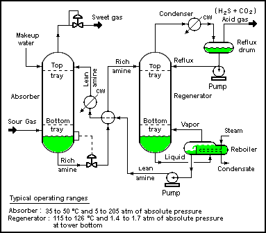
Process flow diagram example
The process flow diagram below depicts a single chemical engineering unit process known as an amine treating plant:
Article Source : Instreng


I need document of yokogawa dcs for control room operator
Best regards
Get here
https://instrumentationforum.com/t/yokogawa-dcs-cs3000-training-pdf/10894