This is the PLC Program for Alarm Security Systems. Learn the PLC programming with this example problem.
Alarm Security System
Problem Description
Make burglar alarm system program in S7-1200 PLC for the house.
Consider one house, in this we want to arrange automatic burglar alarm security system. Alarm should be ON when any person will be detected by the motion sensor.
Problem Diagram

Problem Solution
We can solve this problem by using simple logic. Here we can use two sensors, one motion sensor and second window sensor. Window sensor is the loop of wires.
The motion sensor is designed such that when person is detected in a house or room, then the sensor will be activated (change its state to 1 or true)
Here important point in window sensor is that current is always passing until the breakage occurs in the glass. Hence output always true and when someone will try to break the window glass, current will not flow in the circuit.
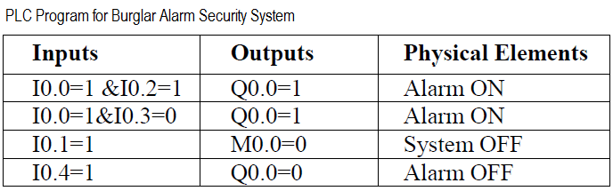
List of Inputs and Outputs
Inputs List
- System START :- I0.0
- System STOP :- I0.1
- Motion detector :- I0.2
- Window sensor :- I0.3
- Alarm stop button :- I0.4
Outputs List
- Alarm :- Q0.0
M Memory
- M0.0 :- Master coil.
- M0.1 :- Alarm on condition.
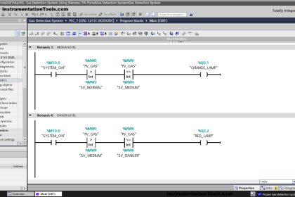
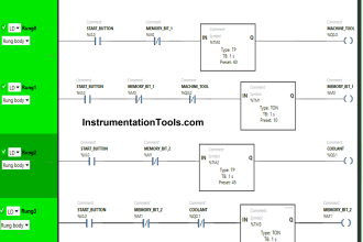
PLC Ladder Diagram for Alarm Security System
Program Description
In this problem we will consider S7-1200 PLC and TIA portal software for programming.
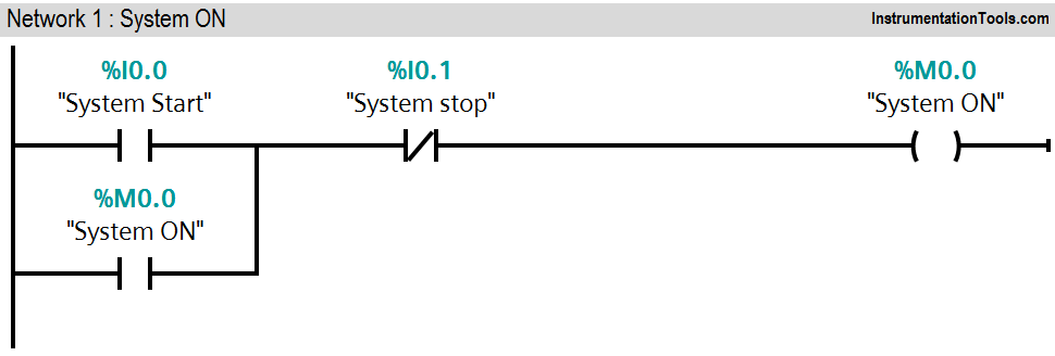
Network 1:
This network shows simple latching circuit for system ON and system OFF.
we used Normally Open (NO) contact of system START button (I0.0) and NC contact of system STOP button (I0.1) for system activation.
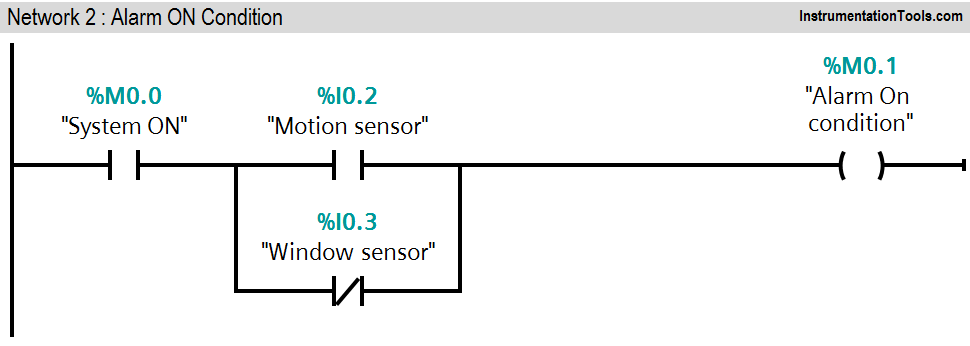
Network 2:
When system is activate and motion sensor (I0.2) detects the person entry, alarm on (M0.1) condition will be ON and it will activate the alarm (Q0.0).
Normally NC contact of window sensor (I0.3) is used in parallel so in normal condition it is true. If breakage of glass or window condition is detected, window sensor (I0.3) input goes false and it will activate the alarm condition (M0.1).
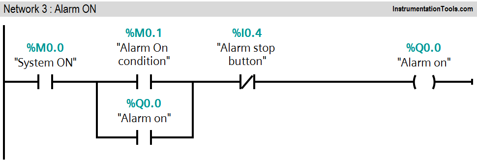
Network 3:
In this network latching circuit is used for alarm (Q0.0). If alarm condition is detected (M0.1), alarm will be ON and it can be stopped by pressing alarm STOP PB (I0.4).
Note :- Above logic is for explanation purpose only. We can implement this example by using hard wired relay logic also. S7-1200 PLC system is so costly for this simple system.
Result
Author: Bhavesh
If you liked this article, then please subscribe to our YouTube Channel for PLC and SCADA video tutorials.
You can also follow us on Facebook and Twitter to receive daily updates.
Read Next:
- PLC Program for Motor Starter
- Analog Input Sampling in PLC
- Positive Edge Output for One Cycle
- Automatic Liquid Mixing Application
- PLC Program START & STOP Buttons