Topology involves the manner in which the fieldbus devices are connected to the data highway. There are several possible topologies that are employed as per the needs of the plant geography.
Fieldbus Network Topologies
Several options employed are as follows: point-to-point, bus with spurs (multidrop), tree or chicken foot, daisy chain, and mixed. For clarity, power supply and terminators are not shown in the Below Figures representing different fieldbus technologies.
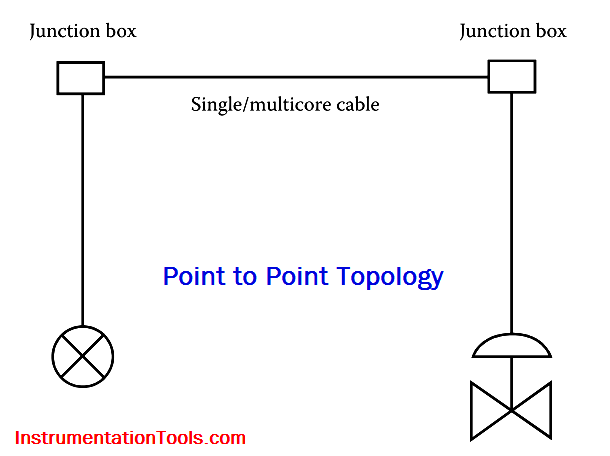
Point to Point Topology
Point-to-point topology is illustrated in Below Figure. In this topology, the segment consists of two devices. The two devices could be in the field, or else the device in the field and the host in the control room.
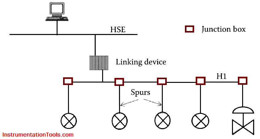
Bus with Spurs
A bus with spurs, also known as multidrop, is shown in Below Figure. The devices are connected to the segment via small cable lengths, called spurs. Spur length can vary between 1 and 120 m.
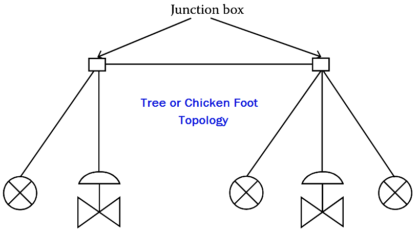
Tree or Chicken Foot Topology
In this topology, devices on a particular segment are connected via a junction box, marshaling panel, terminal, or I/O card (also called chicken foot).
This scheme is suitable for devices situated in the same geographical place and can be connected to the same junction box and also obeying the rules of maximum spur length per segment. The scheme is shown in Below Figure.
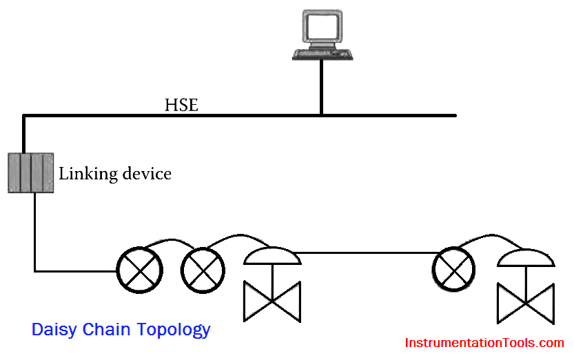
Daisy Chain Topology
This is shown in Below Figure in which the devices are series connected in a particular segment.
Device connections to the segment should be such that dis-connection of a single segment would not lead to total isolation of that segment.
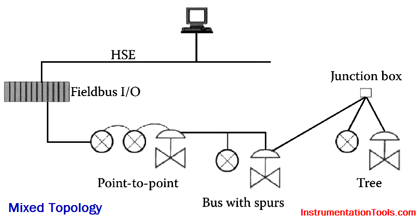
Mixed Topology
A mixed topology embraces more than one topology discussed above, and a possible combination is shown in Below Figure.
Depending on the physical locations of the devices in the plant and the length restrictions for segment lengths, different topologies are employed to derive the advantages of individual topologies.