ISO/OSI Model
The International Standards Organization (ISO) has determined a general architecture of network specifications in their DIS 7498 model (applicable to most any digital network). These network specifications were developed as part of the Open Systems Interconnection (OSI) initiative to define the layering of communications in network protocol design. The OSI protocol stack is split into seven layers for modularity. All of the software layers work together, building and distributing the communications. Not all network protocols use every layer.
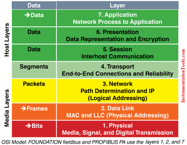
Digital fieldbus systems (FOUNDATION fieldbus and PROFIBUS PA) use three of the seven layers: 1, 2, and 7. This is because physical and logical layers are the same and there is no direct communication from one node to another across different segments.
The Layers in Detail
■ Level 1 – Physical Layer: Defines the electrical and physical specifications for devices. In particular, the physical layer defines the relationship between a device and a physical medium. This relationship includes the layout of pins, voltages, and cable specifications.
■ Level 2 – Data Link Layer: Is the protocol layer that transfers data between adjacent network nodes in a wide area network or between nodes on the same segment. The Data Link Layer provides the functional and procedural means to transfer data between network entities and provides the means for error detection and correcting events that occur in the physical layer.
■ Level 3 – Network Layer: Establishes procedures for the encapsulation of data into packets for transmission and reception.
■ Level 4 – Transport Layer: Defines how complete data files are handled over a network.
■ Level 5 – Session Layer: Organizes data transfer in terms of the start and end of a specific transmission.
■ Level 6 – Presentation Layer: Defines the character sets, terminal control, and graphics commands so that abstract data can be readily encoded and decoded between communicating devices.
■ Level 7 – Application Layer: Refers to standards for generating and/or interpreting communicated data in its final form. In other words, the actual software programs used to communicate data.
Also Read: HART vs Foundation Fieldbus


Aside from the issues of the physical network (signal types and voltage levels, connector pinouts, cabling, topology, etc.), there needs to be a standardized way in which communication is arbitrated between multiple nodes in a network, even if its as simple as a two-node, point-to-point system. When a node “talks” on the network, it is generating a signal on the network wiring, be it high and low DC voltage levels, some kind of modulated AC carrier wave signal, or even pulses of light in a fiber. Nodes that “listen” are simply measuring that applied signal on the network (from the transmitting node) and passively monitoring it. If two or more nodes “talk” at the same time, however, their output signals may clash (imagine two logic gates trying to apply opposite signal voltages to a single line on a bus!), corrupting the transmitted data.
The standardized method by which nodes are allowed to transmit to the bus or network wiring is called a protocol. There are many different protocols for arbitrating the use of a common network between multiple nodes, and I’ll cover just a few here. However, its good to be aware of these few, and to understand why some work better for some purposes than others. Usually, a specific protocol is associated with a standardized type of network. This is merely another “layer” to the set of standards which are specified under the titles of various networks.
The International Standards Organization (ISO) has specified a general architecture of network specifications in their DIS7498 model (applicable to most any digital network). Consisting of seven “layers,” this outline attempts to categorize all levels of abstraction necessary to communicate digital data.
Level 1: Physical Specifies electrical and mechanical details of communication: wire type, connector design, signal types and levels.
Level 2: Data link Defines formats of messages, how data is to be addressed, and error detection/correction techniques.
Level 3: Network Establishes procedures for encapsulation of data into “packets” for transmission and reception.
Level 4: Transport Among other things, the transport layer defines how complete data files are to be handled over a network.
Level 5: Session Organizes data transfer in terms of beginning and end of a specific transmission. Analogous to job control on a multitasking computer operating system.
Level 6: Presentation Includes definitions for character sets, terminal control, and graphics commands so that abstract data can be readily encoded and decoded between communicating devices.
Level 7: Application The end-user standards for generating and/or interpreting communicated data in its final form. In other words, the actual computer programs using the communicated data.
Vert well defined at the summary level. Excellent information…