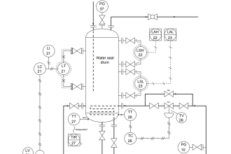
The flow test system shall be as shown in following figure.
It includes:
a) a test specimen;
b) a test section;
c) upstream and downstream throttling valves;
d) a flow measurement device;
e) pressure taps and measuring devices (upstream and downstream);
f) a temperature sensor; and
g) cavitation detection instrumentation shown in figure.
Cavitation Test

Procedure
Step 1:
The test specimen can be any valve or test apparatus for which test data are required.
Step 2:
The test specimen upstream and downstream piping shall conform to the nominal size of the test specimen connection and to the following length requirements.
The upstream pressure tap shall be two nominal pipe diameters from the test specimen connection, while the downstream pressure tap shall be six nominal pipe diameters from the test specimen connection.
There shall be at least 18 nominal pipe diameters of straight pipe (eight if straightening vanes are used) upstream of the upstream pressure tap, and at least one pipe diameter of straight pipe downstream of the downstream pressure tap.
An effort should be made to match the inside diameter at the inlet and outlet of the test specimen with the inside diameter of the adjacent piping.
Also Read: Causes of Cavitation
Step 3:
The upstream and downstream throttling valves are used to control the pressure differential across the test section pressure taps and to maintain a specific downstream pressure.
The downstream valve should be of sufficient capacity to ensure that choked flow (in the case of the standard calibration test manifold) and the other desired cavitation coefficients can be achieved.
Care should be taken to assure that noise or cavitation from these valves during the testing does not influence the test specimen results.
Step 4:
The flow measuring instrument may be any device that meets the required accuracy.
This instrument shall measure the true time average flow rate within an error not exceeding ± 2% of the actual value.
The resolution and repeatability of the instrument shall be within ±0.5%.
Step 5:
All pressure and pressure differential measurements shall be made to an error not exceeding ±2%.
All temperature measurements shall be made to an error not exceeding ± 2 °F (1.1 °C).
Step 6:
An accelerometer shall be rigidly mounted on the test specimen downstream pipe wall. The main sensitivity axis of the accelerometer shall be perpendicular to the pipe axis.
The exact location on the downstream pipe should be determined by test (to obtain maximum vibration sensing); however, one nominal pipe diameter downstream of the test specimen connection is a good starting point.
As the higher frequency vibrations (5-50 kHz) are of interest in this testing, mounting on the lower mass pipe wall (as compared to the flange mounting) will provide improved sensitivity from a high-frequency accelerometer.
Step 7:
Although this testing does not require accurate quantitative acceleration results (±5% required), a piezoelectric or other accelerometer that has a high enough resonant frequency (> 100 kHz) should be used.
This will assure consistent results for the full frequency range being analyzed (5-50 kHz). A vibration preamplifier should be used as recommended by the accelerometer manufacturer.
For ease of data analysis, an optional high pass filter can be used to differentiate the low-frequency noise (< 5 kHz) resulting from the background and turbulent flow and the high-frequency noise resulting from cavitation.
The exact frequency range of interest for each valve type may vary, and it is the responsibility of the valve tester to determine the optimum range of frequencies for evaluation.
Step 8:
The alignment between the centerline of the test section piping and the centerline of the inlet and outlet of the test specimen shall be within 1/16-inch (1.6 mm) for pipe sizes up to NPS 6 (150 mm), and within 1% of the diameter for pipe sizes NPS 8 (200 mm) and larger.
When rotary valves are being tested, the valve shaft shall be aligned with the test section pressure taps. All gaskets should be positioned so that they do not protrude into the flow stream.
Step 9:
Water at relatively constant temperature shall be the basic fluid used in this test procedure.
The water shall be sufficiently free of suspended particles, air, or other gases so as not to affect the test results.
Step 10:
The test section shown in Figure shall be used with the test specimen (valve) set at a specified travel.
Travel positions of 20%, 40%, 60%, 80%, and 100% rated travel, as a minimum, shall be used for a valve, and the following test should be run for each travel position.
Since the parameters being tested are a direct function of valve geometry, additional travel positions for some valves may be needed.
Step 11:
The downstream throttling valve shall be in the fully open position, or in a travel position that provides for cavitating conditions in the test valve.
Then, with a preselected upstream pressure, the flow rate, upstream pressure, the downstream or differential pressure across the test valve, and accelerometer levels shall be recorded.
The use of differential pressure measuring instruments is preferred whenever possible to ensure accuracy. During a test run, P1 shall be held constant to within ± 5%.
This establishes a maximum pressure differential for the test valve in a test system at a particular travel setting.
Step 12:
DO NOT EXCEED THE MAXIMUM PRESSURE DROP RATING OF THE VALVE BEING TESTED.
CARE SHOULD BE TAKEN TO ASSURE THAT GAS IS NOT TRAPPED IN THE DOWNSTREAM PRESSURE TAPS.
Step 13:
A series of additional tests shall be made at subsequently decreasing pressure drops by throttling the downstream throttling valve.
Each test should decrease the test specimen pressure drop by suitable increments to detect inflection points in the vibration curve; and the same recordings of flow, pressure, and acceleration shall be made.
Step 14:
The following data shall be recorded:
Valve travel — measurement error shall not exceed ± 0.5% of rated travel;
Upstream pressure (P1) — instrument measurement error shall not exceed ± 2% of the actual value;
Pressure drop (DP) (preferred) or downstream pressure (P2) — instrument measurement error shall not exceed ± 2% of the actual value;
Measured flow rate (q) — measurement error shall not exceed ± 2% of the actual value;
Fluid temperature (T) — measurement error shall not exceed ± 2 °F (1.1 °C). Care should be taken to monitor and record changes in fluid temperature so that vapour pressure can be properly determined for all test points. This is especially important for recirculating test systems in which fluid temperature may increase during a test.
Downstream pipe wall vibration — measurement error shall not exceed ±5% of full scale. Instrument full scale should be selected for optimum measurement of the range of vibration amplitudes.
Barometric pressure — measurement error shall not exceed ± 2% of the actual value. Convert to absolute pressure (Pa), psia (kPa).
Step 15:
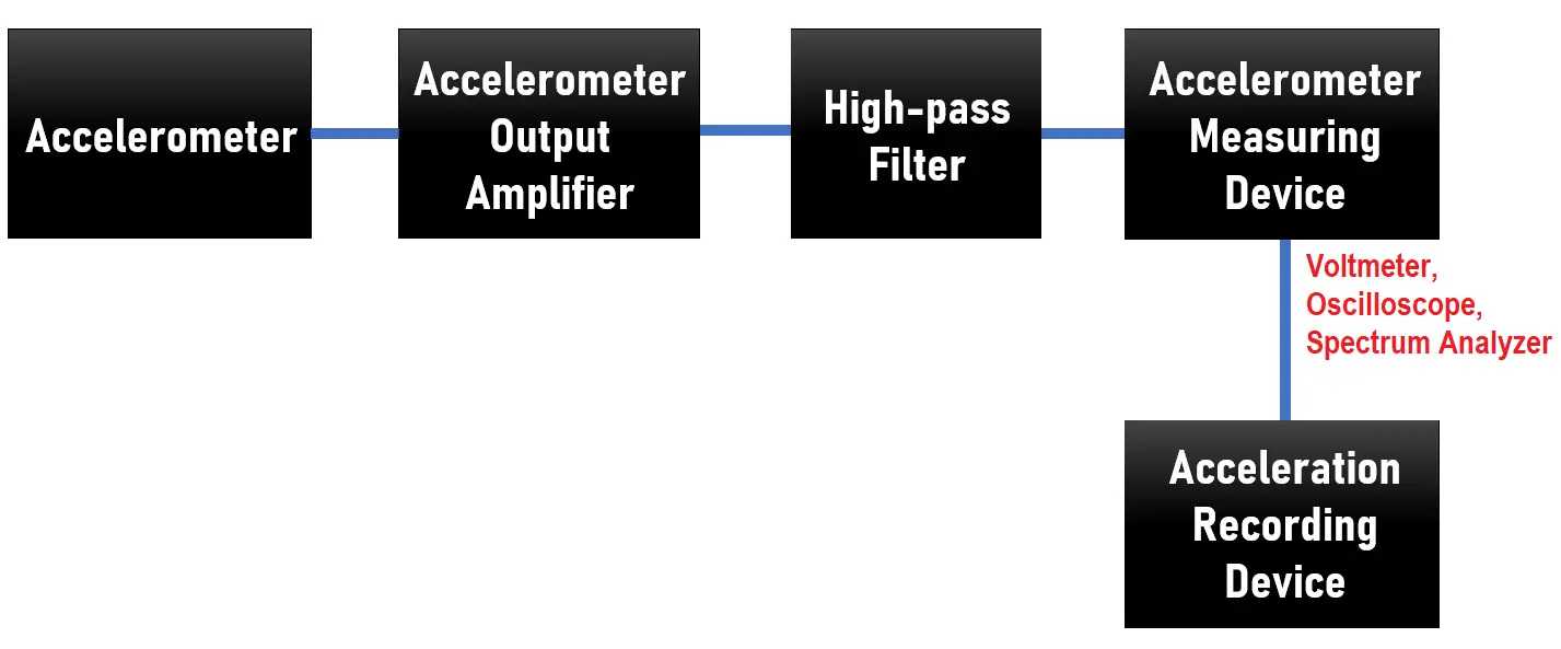
Calculate the average acceleration in G, ft/s2 (m/s2), or equivalent to as high a frequency as permitted by the instrumentation within the frequency range 5-50 kHz.
These data can be obtained from a frequency analyzer, oscilloscope, or voltmeter (with a high-pass filter).
Step 16:
With average acceleration and cavitation coefficient data, we can plot graph for cavitation.
Read Next:
- Solenoid Valve and PLC
- Select a Control Valve
- Control Valves Checklist
- Valve Stroke Test
- Types of Valves Noise