Inst ToolsInst ToolsInst Tools
  • Courses
  • Automation
    • PLC
    • Control System
    • Safety System
    • Communication
    • Fire & Gas System
  • Instrumentation
    • Design
    • Pressure
    • Temperature
    • Flow
    • Level
    • Vibration
    • Analyzer
    • Control Valve
    • Switch
    • Calibration
    • Erection & Commissioning
  • Interview
    • Instrumentation
    • Electrical
    • Electronics
    • Practical
  • Q&A
    • Instrumentation
    • Control System
    • Electrical
    • Electronics
    • Analog Electronics
    • Digital Electronics
    • Power Electronics
    • Microprocessor
  • Request
Search
  • Books
  • Software
  • Projects
  • Process
  • Tools
  • Basics
  • Formula
  • Power Plant
  • Root Cause Analysis
  • Electrical Basics
  • Animation
  • Standards
  • 4-20 mA Course
  • Siemens PLC Course
Reading: PID Controller Gains Effect on Manipulated Variable
Share
Notification Show More
Font ResizerAa
Inst ToolsInst Tools
Font ResizerAa
  • Courses
  • Design
  • PLC
  • Interview
  • Control System
Search
  • Courses
  • Automation
    • PLC
    • Control System
    • Safety System
    • Communication
    • Fire & Gas System
  • Instrumentation
    • Design
    • Pressure
    • Temperature
    • Flow
    • Level
    • Vibration
    • Analyzer
    • Control Valve
    • Switch
    • Calibration
    • Erection & Commissioning
  • Interview
    • Instrumentation
    • Electrical
    • Electronics
    • Practical
  • Q&A
    • Instrumentation
    • Control System
    • Electrical
    • Electronics
    • Analog Electronics
    • Digital Electronics
    • Power Electronics
    • Microprocessor
  • Request
Follow US
All rights reserved. Reproduction in whole or in part without written permission is prohibited.
Inst Tools > Blog > Animation > PID Controller Gains Effect on Manipulated Variable

PID Controller Gains Effect on Manipulated Variable

Last updated: October 5, 2018 4:50 pm
Editorial Staff
Animation Control Systems
1 Comment
Share
1 Min Read
SHARE

Observe the Effect of Proportional Gain Kp, Integral Gain Ki and Derivative Gain Kd values with respect to PID Controller Output response shown in below animation.

The below graph shown is PID Controller output response on a change in error signal. Consider the error signal is same and observe the controller output response with change in different PID controller gains.

  • Dotted Line – Setpoint
  • Blue Colour Line – PID Controller Output
  • Kp, Ki, Kd are PID Controller Gains

PID Controller Response
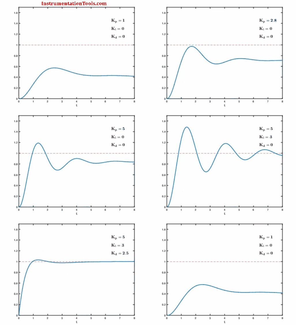
PID Controller Gains Effect on Setpoint

Also Read: Why Bias used in Proportional Controller ?

Don't Miss Our Updates
Be the first to get exclusive content straight to your email.
We promise not to spam you. You can unsubscribe at any time.
Invalid email address
You've successfully subscribed !

Continue Reading

Managed Switch vs Unmanaged Switch
How is Data Stored in Standard Modbus Protocol?
How to Do Loop Checks During Plant Pre-Commissioning
What is Multi-touch Technology? – Industrial Automation
How a Level Switch Works
What is 21 CFR in SCADA and HMI Systems?
Share This Article
Facebook Whatsapp Whatsapp LinkedIn Copy Link
Share
1 Comment
  • anu says:
    October 12, 2016 at 7:58 pm

    Thank you sir…. very useful …..

    Reply

Leave a Reply Cancel reply

Your email address will not be published. Required fields are marked *

Stay Connected

128.3kFollowersLike
69.1kFollowersFollow
210kSubscribersSubscribe
38kFollowersFollow

Categories

Explore More

Nutating Disc Flow Meters Working Principle
On/off Control Theory
Instrumentation Engineer Activities & Documents – Detail Design Phase
Configuration of PlantPAx Library in Factory Talk Studio
Proportional Integral Derivative Controllers – PID MCQ
Magnetic Level Indicators Working Animation
Motor Control Signal Interface
Design Document for Project Systems Architecture

Keep Learning

ESD System Insights

ESD System Insights: Signals for Emergency Valve Shutdown Explained

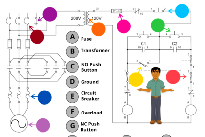
Electrical Circuit Label Schematic

Label the Electrical Circuit Schematic

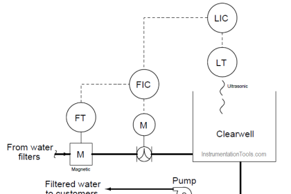
LIC and FIC Controllers

What LIC and FIC Controllers will do?

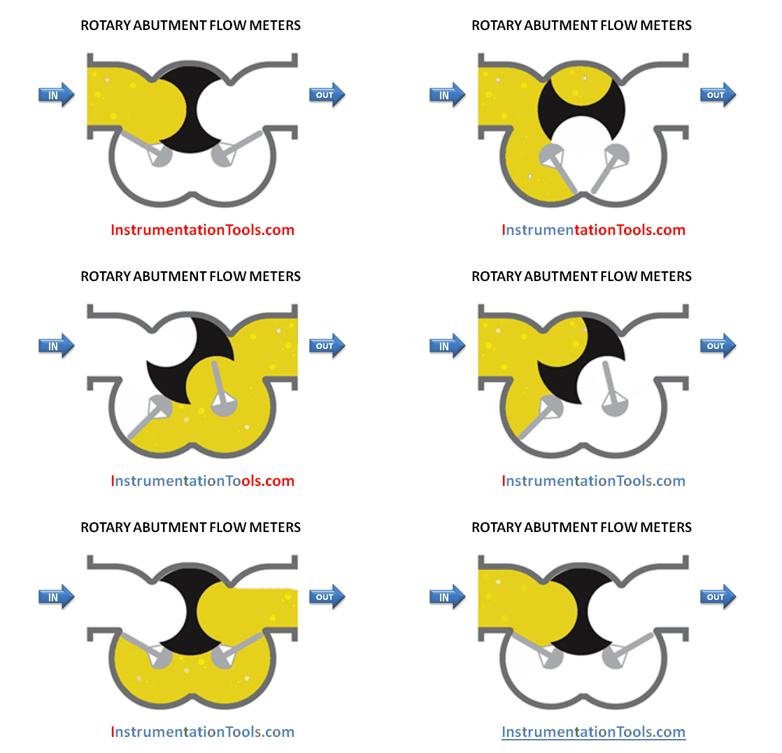
ROTARY ABUTMENT FLOW METERS WORKING ANIMATION

Rotary Abutment Flow Meters Working Principle and Animation

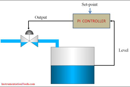
Integral Wind-Up Limitation

What is Integral Wind Up ?

DCS Commissioning Steps

DCS Commissioning Steps

Technical Evaluation for DCS and ESD - Distributed Control System

Technical Evaluation for DCS and ESD – Distributed Control System

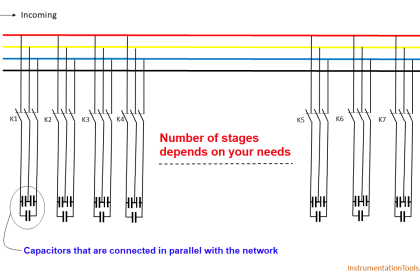
power factor correction equipment

Power Factor Controller (PFC) – Commissioning

Learn More

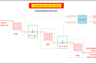
Superheated Steam Temperature Control System

Superheated Steam Temperature Control System

ATEX Ratings, Intrinsic Safety, Hazardous Areas and Explosive Atmospheres

ATEX Ratings, Intrinsic Safety, Hazardous Areas and Explosive Atmospheres

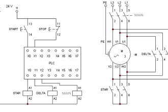
PLC Motor Control Ladder Logic

PLC Program for Star Delta Motor Starter

Ion Analyzers Questions and Answers

Special Designs of Ion Selective Electrodes Questions & Answers

Flow Meter Questions and Answers

Flow Meter Questions and Answers

Differential Pressure Level Transmitter Errors

Differential Pressure Level Transmitter Errors

PLC Programmer Unknown Do's

Unknown Do’s Need to Know as a PLC Programmer

4-20mA Current Loop for Flow Transmitter and Control Valve Positioner

4–20 mA Process Control Loops

Menu

  • About
  • Privacy Policy
  • Copyright

Quick Links

  • Learn PLC
  • Helping Hand
  • Part Time Job

YouTube Subscribe

Follow US
All rights reserved. Reproduction in whole or in part without written permission is prohibited.
Welcome Back!

Sign in to your account

Username or Email Address
Password

Lost your password?