Inst ToolsInst ToolsInst Tools
  • Courses
  • Automation
    • PLC
    • Control System
    • Safety System
    • Communication
    • Fire & Gas System
  • Instrumentation
    • Design
    • Pressure
    • Temperature
    • Flow
    • Level
    • Vibration
    • Analyzer
    • Control Valve
    • Switch
    • Calibration
    • Erection & Commissioning
  • Interview
    • Instrumentation
    • Electrical
    • Electronics
    • Practical
  • Q&A
    • Instrumentation
    • Control System
    • Electrical
    • Electronics
    • Analog Electronics
    • Digital Electronics
    • Power Electronics
    • Microprocessor
  • Request
Search
  • Books
  • Software
  • Projects
  • Process
  • Tools
  • Basics
  • Formula
  • Power Plant
  • Root Cause Analysis
  • Electrical Basics
  • Animation
  • Standards
  • 4-20 mA Course
  • Siemens PLC Course
Reading: Batch Mixing with PLC Ladder Logic Program
Share
Notification Show More
Font ResizerAa
Inst ToolsInst Tools
Font ResizerAa
  • Courses
  • Design
  • PLC
  • Interview
  • Control System
Search
  • Courses
  • Automation
    • PLC
    • Control System
    • Safety System
    • Communication
    • Fire & Gas System
  • Instrumentation
    • Design
    • Pressure
    • Temperature
    • Flow
    • Level
    • Vibration
    • Analyzer
    • Control Valve
    • Switch
    • Calibration
    • Erection & Commissioning
  • Interview
    • Instrumentation
    • Electrical
    • Electronics
    • Practical
  • Q&A
    • Instrumentation
    • Control System
    • Electrical
    • Electronics
    • Analog Electronics
    • Digital Electronics
    • Power Electronics
    • Microprocessor
  • Request
Follow US
All rights reserved. Reproduction in whole or in part without written permission is prohibited.
Inst Tools > Blog > PLC Tutorials > Batch Mixing with PLC Ladder Logic Program

Batch Mixing with PLC Ladder Logic Program

In this example, we will learn batch mixing with PLC ladder logic program using timer instructions such as TP, and TON.

Last updated: April 14, 2024 8:40 pm
Editorial Staff
PLC Tutorials
No Comments
Share
5 Min Read
SHARE

In this example, we will learn batch mixing with PLC ladder logic program using timer instructions such as TP, and TON.

Contents
Batch MixingPLC Logic Video TrainingInputs and OutputsPLC Ladder Logic ProgramDescriptionProgram Simulated

Note: The ladder logic is dedicated to students to practice the PLC program with simple examples.

Batch Mixing

Problem Statement:

Design a PLC ladder logic for the following application.

We are using one toggle switch to control a Mixer and valve.

The MIXER runs for 10 seconds, and then a VALVE opens for 5 seconds, allowing ingredients to flow in.

After that the VALVE closes, and the MIXER runs for another 15 seconds.

PLC Logic Video Training

Get the PLC video training series from our YouTube channel and access hundreds of free example programs.

PLC Timer Programming Example based on Batch Mixing

Inputs and Outputs

Digital Inputs:

Start Button: I0.0

Digital Outputs:

Mixer: Q0.0

Valve: Q0.1

PLC Ladder Logic Program
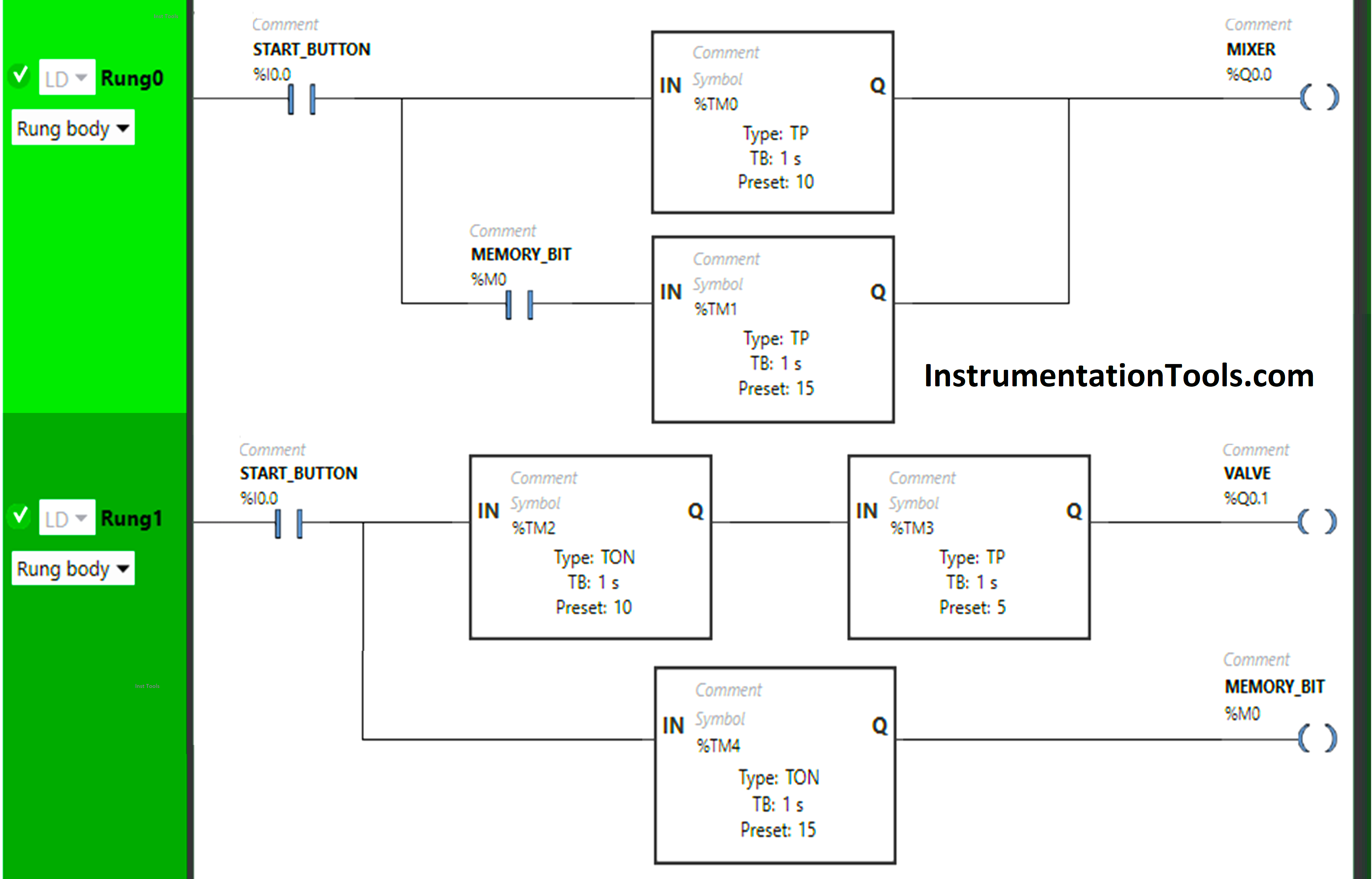
Batch Mixing with PLC Ladder Logic Program

Description

We have used Normally Open Contact for the Start Button (I0.0) and Memory Bit (M0).

In Rung 0:

  • Normally Open Contact is used for the Start Button (I0.0) and Memory Bit to Turn ON the output Mixer (Q0.0).
  • Timer Function Block type TP is used to Turn ON the output Mixer (Q0.0) for a limited time.
  • Time Function Block TON is used to delay the turning ON time of the output Mixer (Q0.0) for some time.

In Rung 1:

  • Normally Open Contact is used for the Start Button (I0.0) to Turn ON the output Valve (Q0.1).
  •  Timer Function Block type TON is used to delay the turning ON time of the output valve (Q0.1) for some time.
  • Timer Function Block type TP is used to Turn ON the output Valve(Q0.1) for a limited time.
  • Timer Function Block type TON is used to delay the turning ON time of Memory Bit (M0) for some time.

Program Simulated

Here we simulate our PLC program. Note that we shown only the simulated part of the logic instead of the complete code. Watch the above video to understand the program.

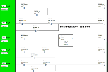
Rung 0:
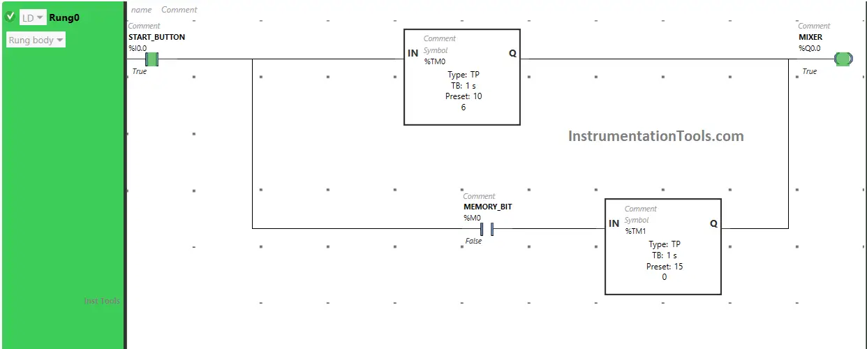
Automatic Batch Mixing Tank

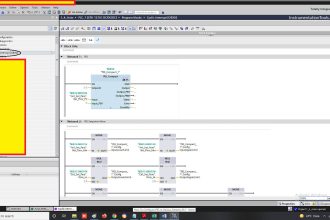
When the Start Button (I0.0) is turned ON, the Mixer immediately turns ON. Also, the Timer starts in Timer Function Block type TP Which turns ON the output Mixer (Q0.0) for a limited time. In this Timer Function Block, time is set to 10 seconds. So, after 10 seconds the output Mixer (Q0.0) will turn OFF.

Rung 1:

When the Start Button is turned ON, the Valve will turn ON after 10 seconds because the Timer Function Block type TON is used to delay the turning ON time of the output Valve (Q0.1), and the time is set to 10 seconds.
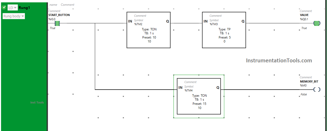
Batching Tank Ladder Logic

The output Valve (Q0.1) will remain ON only for 5 seconds as we have used Timer Function Block type TP to turn ON the output valve (Q0.1) only for a limited time and the time is set to 5 seconds. So after 5 seconds, the output Valve (Q0.1) will turn OFF.
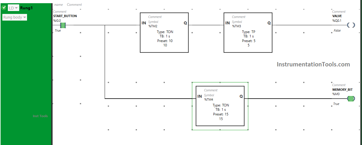
PLC Programming for Batching Station Project

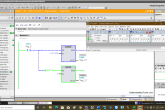
Also, When the Start Button (I0.0) is turned ON, the Memory Bit (M0) will turn ON after 15 seconds as we have used Time Function Block TON to delay the turning ON time of the Memory Bit and time is set to 15 seconds.
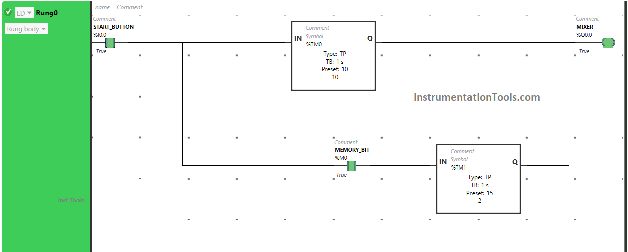
PLC program for a batch process

After 15 seconds, the Memory Bit will turn ON. When Memory Bit turns ON in Rung 1, it will turn ON Memory Bit in Rung 0 also and the output Mixer (Q0.0) will turn ON for 15 seconds as we have used timer function block type TP. So after 15 seconds, the output Mixer (Q0.0) will turn OFF.

If you liked this article, please subscribe to our YouTube Channel for PLC and SCADA video tutorials.

You can also follow us on Facebook and Twitter to receive daily updates.

Read Next:

  • PLC Programming Example with Motor
  • How to Blink Lights in Ladder Logic?
  • Batch Simulator Program using LogixPro
  • Pump Run for 10 seconds & OFF for 20 seconds
  • Compare Batch Process and Continuous Process
Don't Miss Our Updates
Be the first to get exclusive content straight to your email.
We promise not to spam you. You can unsubscribe at any time.
Invalid email address
You've successfully subscribed !

Continue Reading

Procedure for Siemens S7-300 Download from PC to PLC
What are Trends in SCADA?
FIFO Instruction in Allen Bradley PLC Programming
Features of SCADA
PLC Programming in Hindi – Siemens Tia Portal Full Course Free
#4 PLC Best Practices – Use PLC Flags as Integrity Checks
Share This Article
Facebook Whatsapp Whatsapp LinkedIn Copy Link
Share
Leave a Comment

Leave a Reply Cancel reply

Your email address will not be published. Required fields are marked *

Stay Connected

128.3kFollowersLike
69.1kFollowersFollow
210kSubscribersSubscribe
38kFollowersFollow

Categories

Explore More

Tank Filling and Emptying using Intouch Scada Script
PLC Sinking and Sourcing Explanation
Difference between Motion Controller and PLC
Down Counter PLC Program
PLC Digital Input and Digital Output Modules
Structured Text PLC Programming for Two-Tanks Level Application
Alarm Acknowledge using PLC
PLC Program for Continuous Filling Operation

Keep Learning

Top 100 PLC Objective Questions and Answers

Top 100 PLC Objective Questions and Answers

Siemens LOGO PLC Complete Programming Course

Siemens LOGO PLC Complete Programming Course

car parking example logic

Up Down Counter Instruction in PLC

SCADA

Top 100+ SCADA Questions

Download a Ladder logic program to GE PLC

Free Download PLC Book

#10 PLC Best Practices – Assign Register Blocks by Function

Level Transmitter configuration in PLC

Scaling with Parameters (SCP) Instruction in PLC

Instrumentation and Control Project Packages

Instrumentation and Control Project Packages – Detail Engineering

Learn More

What is a Magnetic Field

Difference Between Electric Field and Magnetic Field

Difference Between Contactor and Relay

Difference Between Contactor and Relay

Allen-Bradley MicroLogix PLC Wiring

Programmable Logic Controller (PLC) Questions and Answers – 8

Electrical Drives Animation

Electrical Drives – Modes, Types, Speed Control Applications

Location of Pressure Taps

Design Considerations of Orifice Plate

Impulse Steam Trap

Impulse Steam Trap

Measurement and Instrumentation Objective Questions

Measurements & Instrumentation Quiz – Set 5

Non-Contacting-Radar-Level-Transmitter-Animation

Non Contacting Radar Level Transmitter Animation

Menu

  • About
  • Privacy Policy
  • Copyright

Quick Links

  • Learn PLC
  • Helping Hand
  • Part Time Job

YouTube Subscribe

Follow US
All rights reserved. Reproduction in whole or in part without written permission is prohibited.
Welcome Back!

Sign in to your account

Username or Email Address
Password

Lost your password?