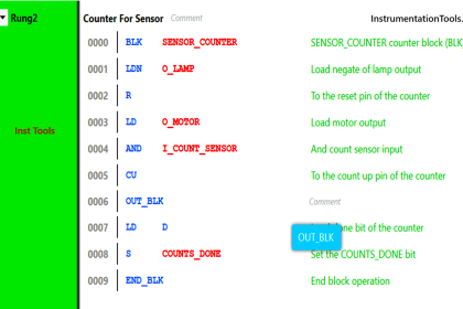
Create PLC programming for pumping and draining for 20 seconds to fill the tank and then drain valve open for 10 seconds.
Note: These PLC programs are designed for students and professionals to learn and practice the ladder logic.
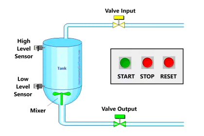
Pumping and Draining System
Problem Statement:
Design a PLC ladder logic for the following application.
We are using two Push Buttons to control the Pump and Drain valve.
When the Start Push Button is pressed and released, the Pump should run for 20 seconds to fill the tank and then the Drain Valve should Open for 10 seconds to drain the tank.
When the Stop Push Button is pressed and released, then the system will stop immediately.
Industrial Automation Solution Videos
Instrumentation Tools prepares the best-in-class industrial automation solution videos for learning purposes for students and professionals.
This video explains the ladder logic programming for pumping and draining.
Inputs/Outputs
Digital Inputs:
Start Push Button: I0.0
Stop Push Button: I0.1
Digital Outputs:
Pump: Q0.0
Drain Valve: Q0.1
PLC Programming
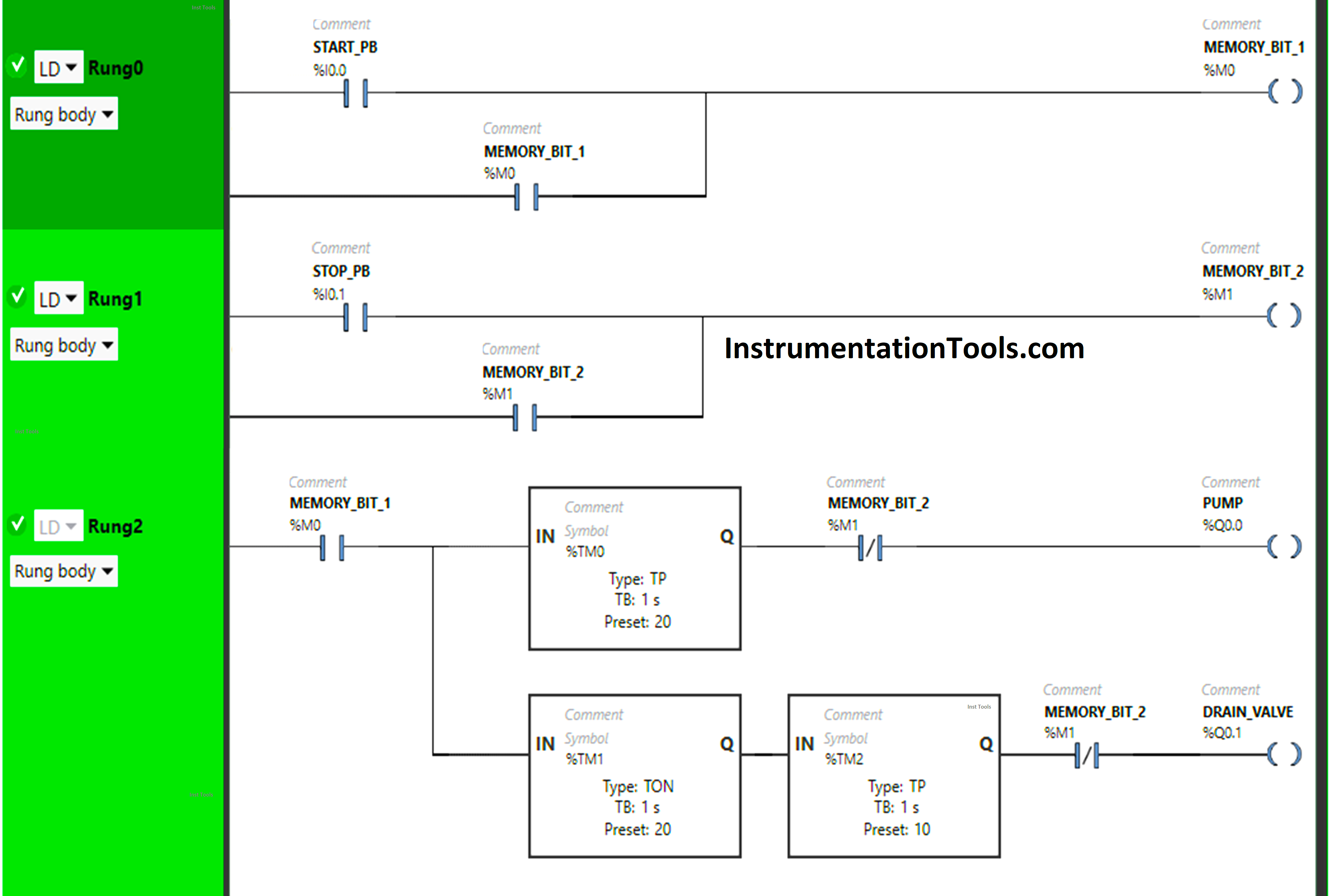
Program Description
We have used Normally Open Contacts for Start Push Button(I0.0), Stop Push Button (I0.1), and Memory Bits.
We have used Normally Closed Contacts for Memory Bit 2 (M1).
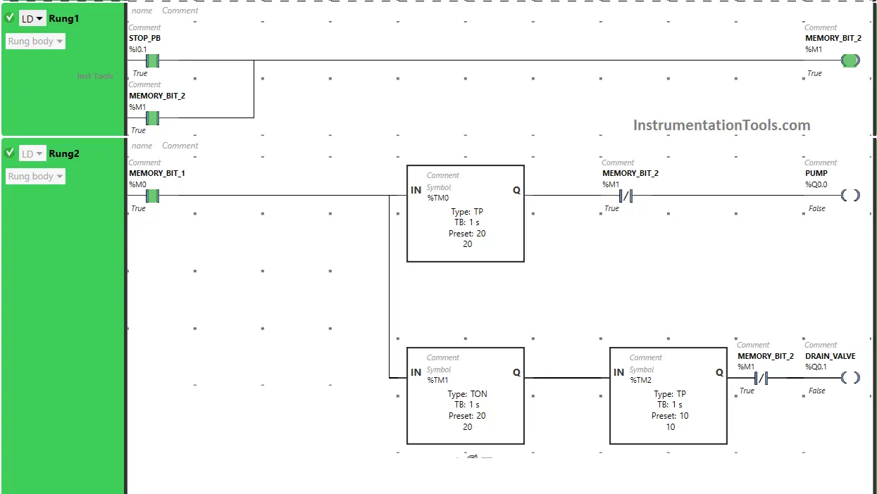
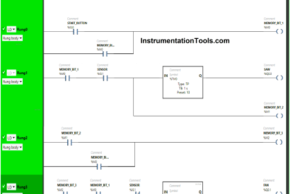
In Rung 0:
- Normally Open Contact is used for the Start Push Button (I0.0) to Turn ON Memory Bit 1 (M0).
- Memory Bit 1 (M0) is latched so that when the Start Push Button (I0.0) turns OFF, Memory Bit 1 (M0) still remains ON.
In Rung 1:
- Normally Open Contact is used for the Stop Push Button (I0.1) to Turn ON Memory Bit 2 (M1).
- Memory Bit 2 (M1) is latched so that when the Stop Push Button (I0.1) turns OFF, Memory Bit 2 (M1) still remains ON.
In Rung 2:
- Normally Open Contact is used for Memory Bit 1 (M0) to Turn ON the outputs Pump (Q0.0) and Drain Valve(Q0.1).
- Timer TP is used to Turn ON the output Pump (Q0.0) for a limited time.
- Timer TON is used to delay the turning ON time of the output Drain Valve (Q0.1) for some time.
- Timer TP is used to Turn ON the output Drain Valve (Q0.1) for a limited time.
- Normally Closed Contacts are used for Memory Bit 2 (M1) to turn OFF the output Pump (Q0.0) and Drain Valve (Q0.1).
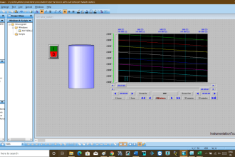
PLC Simulation
Let’s simulate our PLC program and analyze the results. Take note that we may show part of the logic instead of complete code.
When the Start Push Button is pressed and released
When the Start Push Button (I0.0) is pressed and released, Memory Bit 1 (M0) turns ON. Memory Bit 1 (M0) is latched so that when the Start Button (I0.0) is released, Memory Bit 1 (M0) still remains ON.
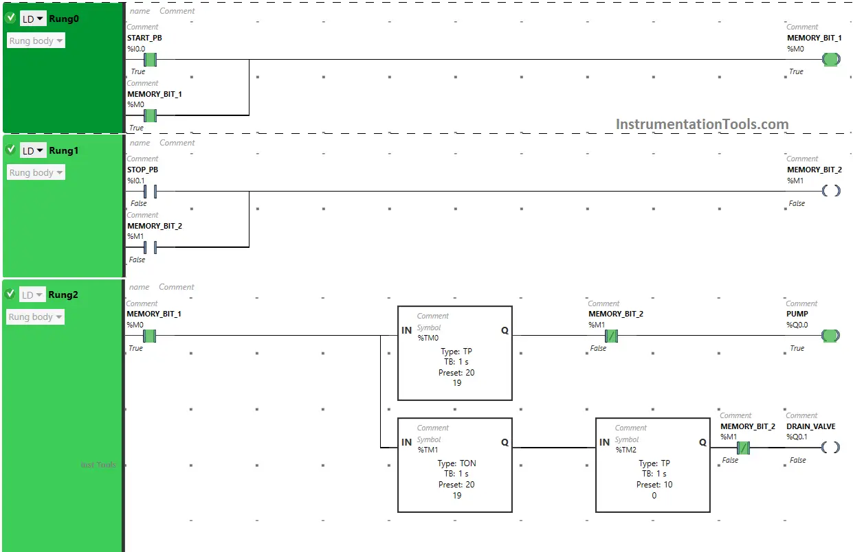
When Memory Bit 1 (M0) turns ON in Rung0, Normally Open Contact used for Memory Bit 1 (M0) will be in True state and pass the signal through it and the output Pump (Q0.0) turns ON but for a limited time as Timer Function Block type TP is used to Turn ON the output Pump (Q0.0) for a limited time and the time set to 20 seconds.
In a false state, Normally Closed Contact used for Memory Bit 2 (M1) passes the signal to turn ON the output Pump (Q0.0). So after 20 seconds, the output Pump (Q0.0) will turn OFF.
Also, when Memory Bit 1 (M0) turns ON, the output Drain Valve (Q0.1) will turn ON after 20 seconds (i.e immediately when the output Pump (Q0.0) turns OFF) as Timer Function Block TON is used to delay the turning ON time of the output Drain Valve (Q0.1).
The time is set to 20 seconds. In a false state, Normally Closed Contact used for Memory Bit 2 (M1) passes the signal to turn ON the output Drain Valve (Q0.1).
So after 20 seconds, the output Drain Valve (Q0.1) will turn ON but for a limited time as Timer Function Block type TP is used to turn ON the output Drain Valve (Q0.1) for a limited time. The time is set to 10 seconds. So after 10 seconds, the output Drain Valve (Q0.1) will turn OFF.
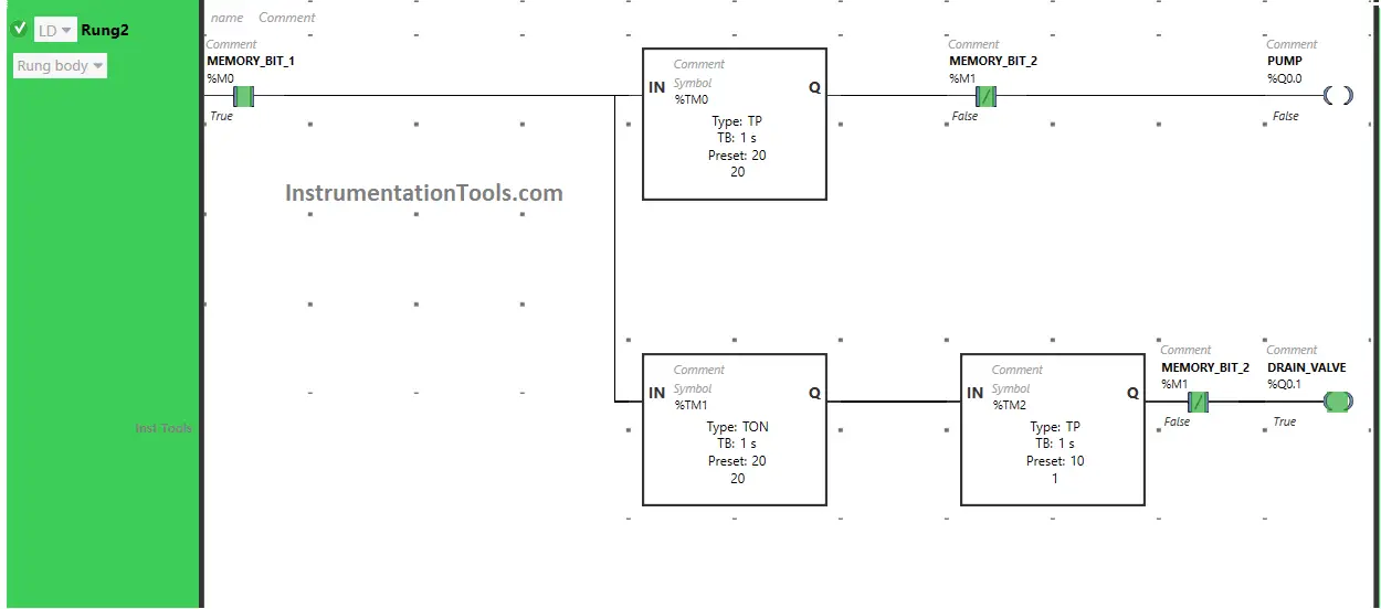
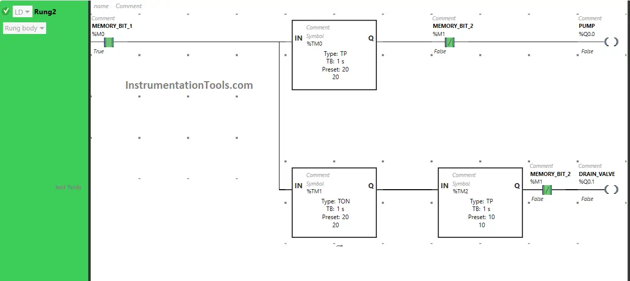
When the Stop Push Button is pressed and released
When the Stop Push Button (I0.1) is pressed and released, Memory Bit 2 (M1) turns ON. Memory Bit 2 (M1) is latched so that when the Stop Push Button (I0.1) is released, Memory Bit 2 (M1) still remains ON.
When Memory Bit 2 (M1) turns ON in Rung1, Normally Closed Contacts used for Memory Bit 2 (M1) in Rung2 will be in a True state and will not allow the signal to pass through it and the outputs Pump (Q0.0), and Drain Valve (Q0.1) will turn OFF immediately.
If you liked this article, please subscribe to our YouTube Channel for PLC and SCADA video tutorials.
You can also follow us on Facebook and Twitter to receive daily updates.
Read Next:
- Valve Logic in Siemens PLC Programming
- PLC Scaling Program for Control Valve
- PLC Programming for Pneumatic Valves
- PLC Program to Drain Product from Tank
- Control Valves PLC Ladder Programming
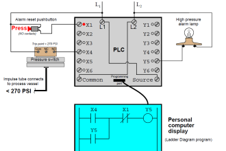

I worry sometimes about using latches in control circuitry. Primarily, my instructions
for programming state. ” What will your Program do, when power goes out ” Do you want a machine to start again as if nothing has happened, or should you use Seal in circuits that necessitate someone re-establishing the machine operation ?