A faceplate is a graphical interface for a specific device or process used in conjunction with PLC and SCADA systems. Faceplates allow operators to monitor and interact with the PLC system efficiently. Learn how to create a faceplate in FactoryTalk View Studio.
When you are working in an HMI or SCADA software, you always require a faceplate to make your work easy. Faceplates are graphical objects where a common screen is developed and you just create multiple instances of this screen by only changing the tags.
For example, if you have 5 motors with the same data, then just create a single motor screen and call different motors from this same screen by just triggering different tags.
Now, one of the most used software in industrial automation is Rockwell Automation. It has an HMI / SCADA software called FactoryTalk View Studio, which many PLC programmers are familiar with. In this too, we can create faceplates for our purpose.
In this post, we will see how to create faceplates in FactoryTalk View Studio.
Faceplate in FactoryTalk View Studio
In the below steps, we discussed the procedure for creating a faceplate in the software.
Step 1:
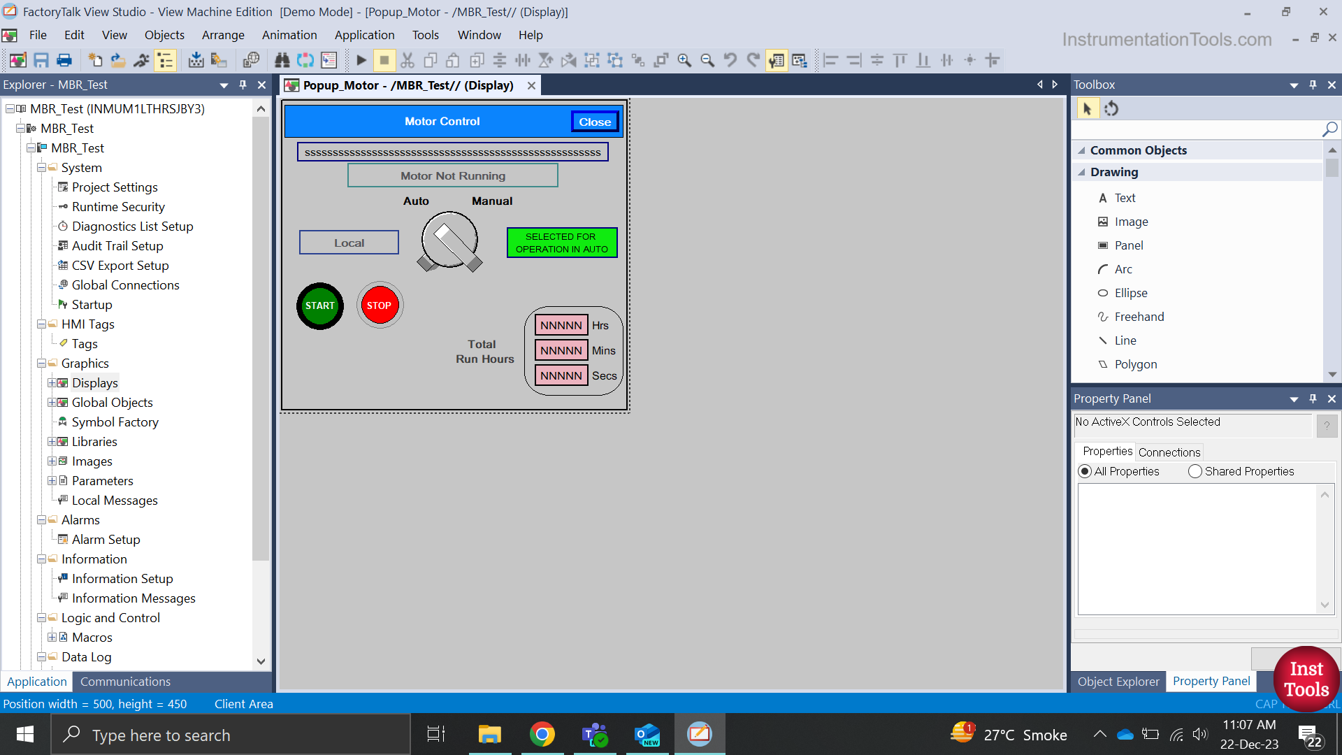
First, create a new screen in a blank project. Refer to the image below. This is a simple motor faceplate having the following data: name, status, auto-manual selection, local-remote status, start button, stop button, mode status and total running hours.
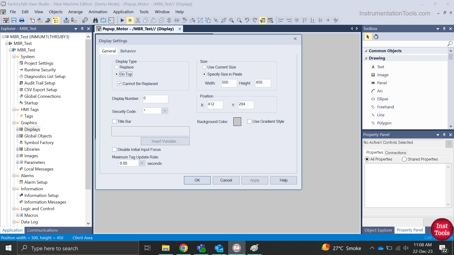
Refer to the below image. These are the properties that you have to set by right-clicking the screen when open. On Top means it can be shown over an existing screen. This is the general property of a popup, where it must overwrite an existing open screen.
Also, tick the option – cannot be replaced. This means that you cannot open any other screen without closing this first. This one is optional and depends on operator requirements. Keep the tag update rate to 0.05 seconds, which is the fastest of all.
Again, this one is optional based on how fast you want to show data to the operator. Then, specify the height and width of the screen and also define the position where it will open.
Step 2:
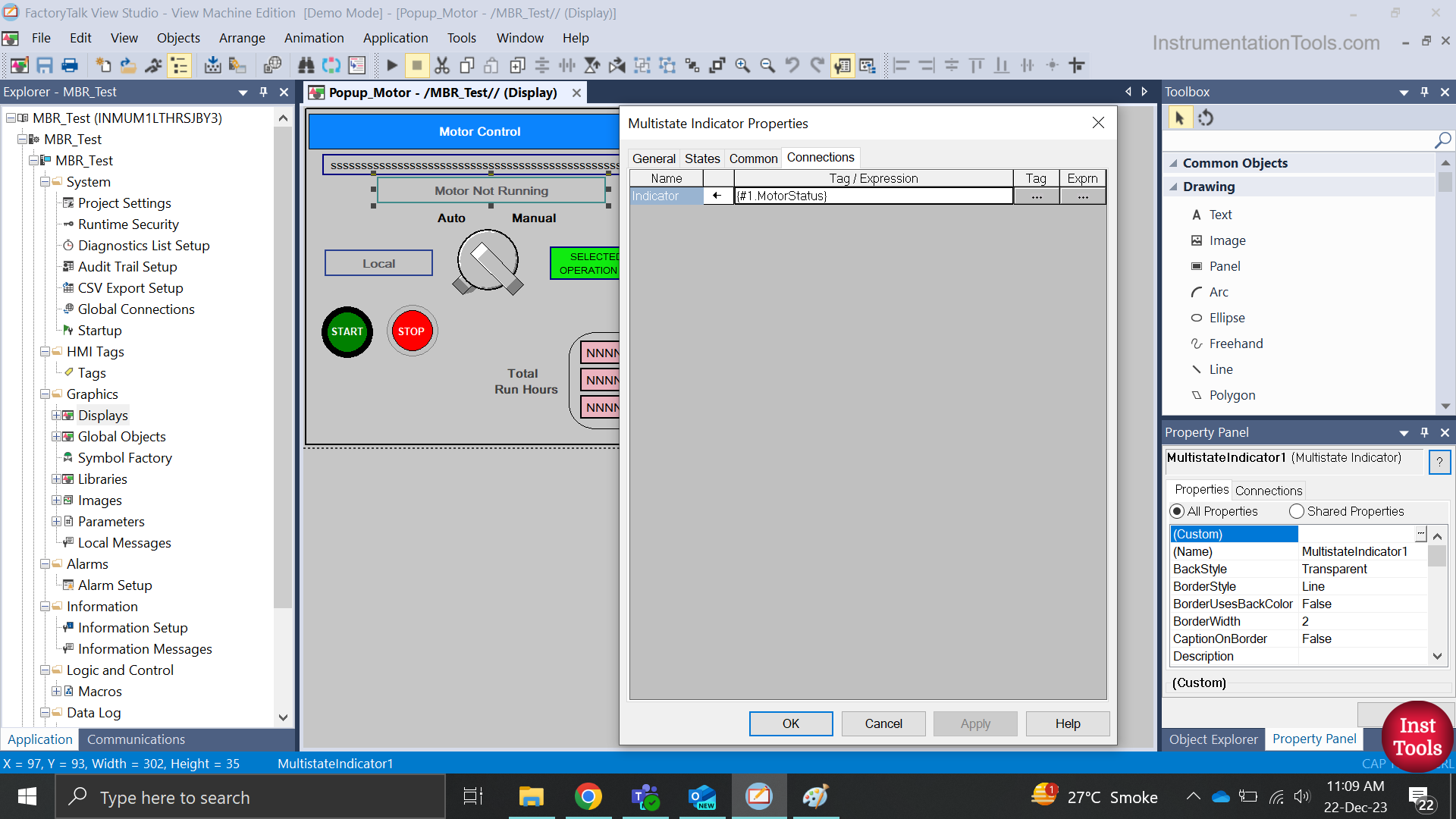
Now, let us have a look at the properties of the objects inside the screen. Take an object showing motor status for example, as shown in the first image.
In the connections tab, you can see that the written format is – {#1.MotorStatus}. What does this mean? Basically, suppose there are four objects on a screen.
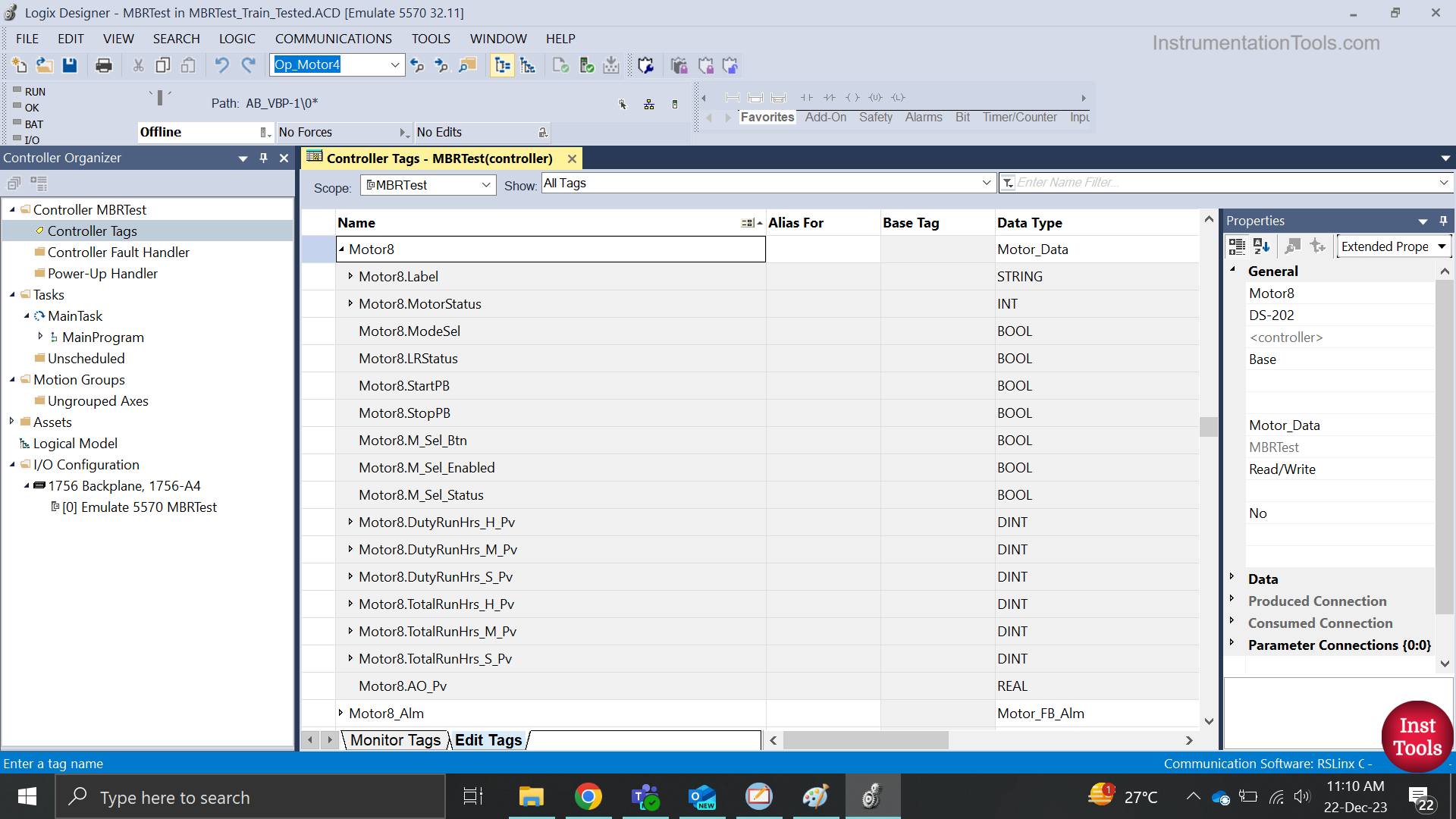
In the PLC program, #1 will be a structured tag with elements in it. Refer to the second image. In this, a tag named Motor8 is created in PLC with a user-defined data type – Motor_Data. This type has various elements inside it as can be seen, like Label, MotorStatus, StartPB etc. In this example, I have 8 motors with the same data. So, I created this data type in the PLC program for simplicity.
So here, #1 will refer to the Motor8 tag. Now, #1.MotorSatus means you are referring to this data. Similarly, the screen has other objects like {#1.StartPB}, {#1.StopPB}, {#1.Label} etc.
In this way, you have to tag objects according to your requirements. In another simple way, if there are single tags in your PLC project, you can also tag them as #1, #2, #3, and so on. The meaning is the same, only the way of defining it is different.
Step 3:
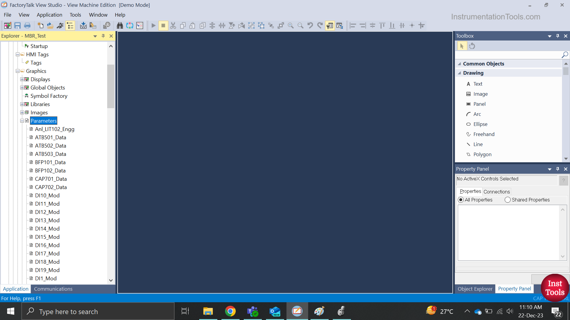
Now, we will create different motor tags for defining on a single screen. Refer to the below image. In the software, where the left-hand toolbar has all the properties, you will find an option named parameters. Here, you have to create parameters.
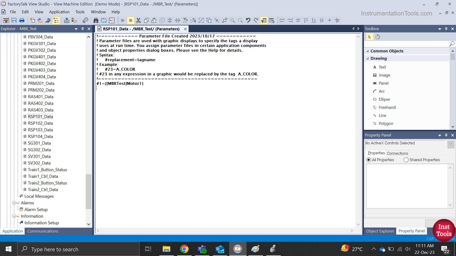
Basically, these are pointers to the screen that you will call and thus, they will have their corresponding data. For example, we will define motor-1 as seen in the second image.
The tag – Motor1 is of data type – Motor_Data which we discussed earlier. We have named this parameter file as – RSP101_Data. Here, we are moving Motor1 tag to #1 which we defined earlier.
Step 4:
Now, let us move to the next step where we will call different motors.
Refer to the below image. There are four motors on the screen. Note that this screen is a replace type, not an on top display.
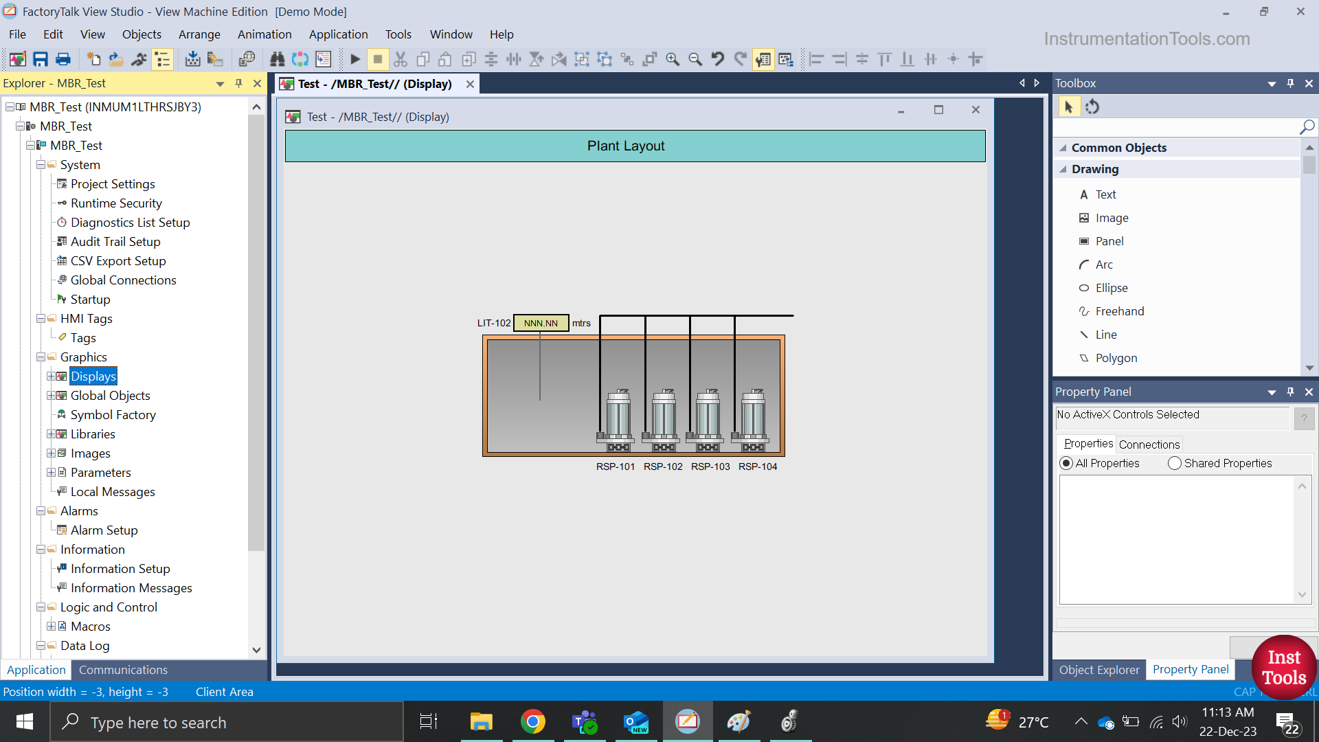
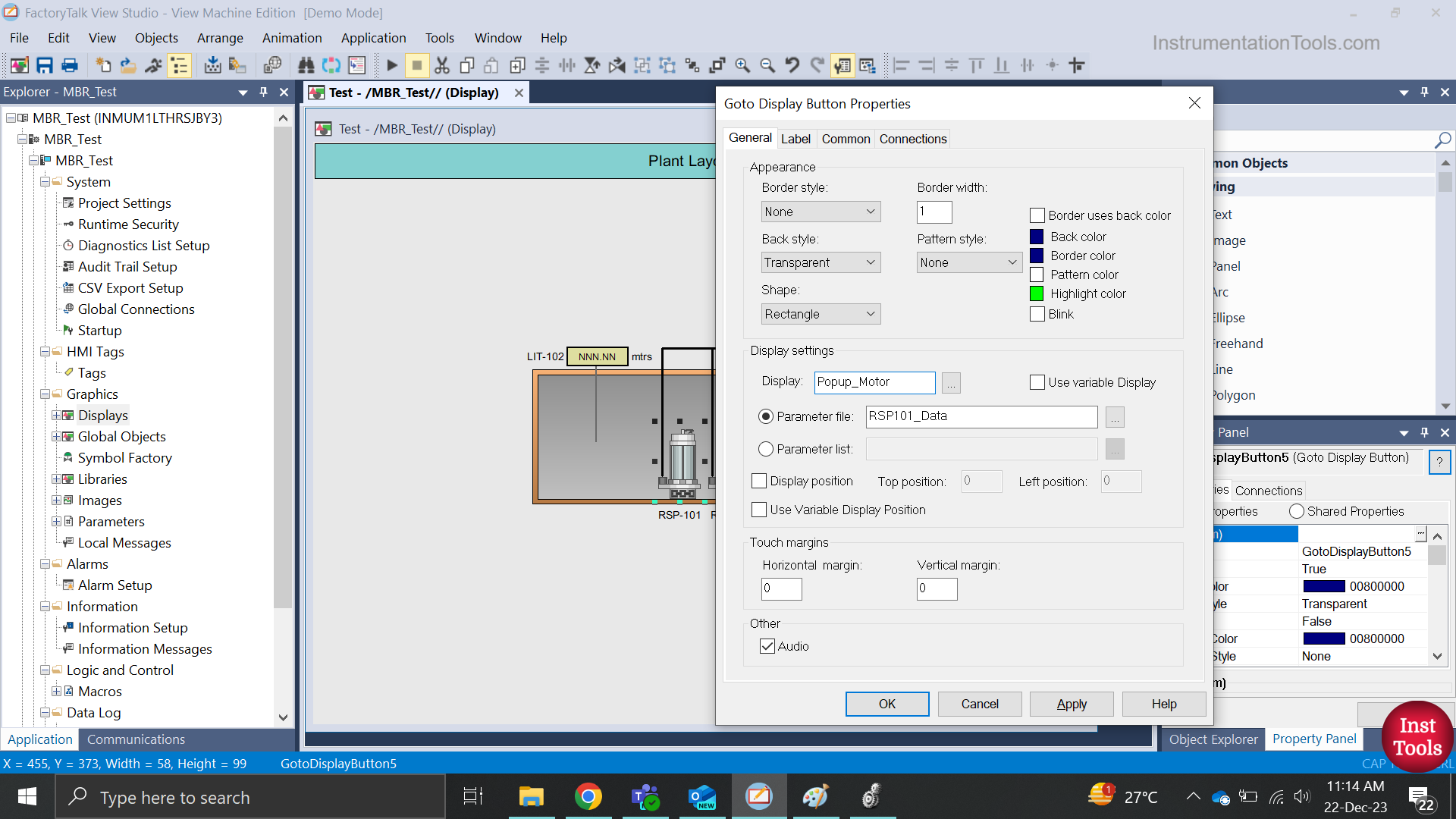
Now, let us take the first motor for example – RSP101; and refer to the image below for its properties. It is an invisible navigation button, overlapped on a motor symbol. It navigates to the page – Popup_Motor, which we created initially. It means on clicking the motor symbol, our popup will open.
Now, the main question is how to call motor-1 or motor-2 and so on. You will see an option – parameter file. There, you have to link the parameter file created earlier, which has motor-1 data (RSP101_Data).
This means that whenever you click the motor-1 symbol, our created popup/faceplate will appear which will move motor-1 data in it. Similarly, link other motors with their corresponding parameter files.
Step 5:
Now, at runtime, whenever you click the motors, the faceplate will open with corresponding data moved from parameter files. It’s very simple and you just have to define the data and screens properly.
If you found this article informative and engaging, we encourage you to consider subscribing to our YouTube Channel, where you can access video tutorials covering topics such as Instrumentation, Electrical, PLC, and SCADA.
For daily updates and to stay connected with our latest content, be sure to follow us on Facebook and Twitter.
To further expand your knowledge, we recommend checking out our next insightful articles.
Read Next:
- PLC Program using Karnaugh Maps
- Solid State vs Electromechanical Relays
- How to use an SQL Server with HMI?
- Types of Siemens PLC Panel Racks
- Basic PLC Ladder Program Example