Inst ToolsInst ToolsInst Tools
  • Courses
  • Automation
    • PLC
    • Control System
    • Safety System
    • Communication
    • Fire & Gas System
  • Instrumentation
    • Design
    • Pressure
    • Temperature
    • Flow
    • Level
    • Vibration
    • Analyzer
    • Control Valve
    • Switch
    • Calibration
    • Erection & Commissioning
  • Interview
    • Instrumentation
    • Electrical
    • Electronics
    • Practical
  • Q&A
    • Instrumentation
    • Control System
    • Electrical
    • Electronics
    • Analog Electronics
    • Digital Electronics
    • Power Electronics
    • Microprocessor
  • Request
Search
  • Books
  • Software
  • Projects
  • Process
  • Tools
  • Basics
  • Formula
  • Power Plant
  • Root Cause Analysis
  • Electrical Basics
  • Animation
  • Standards
  • 4-20 mA Course
  • Siemens PLC Course
Reading: PLC Motor Operation based on Time Cycle Sequence – Program
Share
Font ResizerAa
Inst ToolsInst Tools
Font ResizerAa
  • Courses
  • Design
  • PLC
  • Interview
  • Control System
Search
  • Courses
  • Automation
    • PLC
    • Control System
    • Safety System
    • Communication
    • Fire & Gas System
  • Instrumentation
    • Design
    • Pressure
    • Temperature
    • Flow
    • Level
    • Vibration
    • Analyzer
    • Control Valve
    • Switch
    • Calibration
    • Erection & Commissioning
  • Interview
    • Instrumentation
    • Electrical
    • Electronics
    • Practical
  • Q&A
    • Instrumentation
    • Control System
    • Electrical
    • Electronics
    • Analog Electronics
    • Digital Electronics
    • Power Electronics
    • Microprocessor
  • Request
Follow US
All rights reserved. Reproduction in whole or in part without written permission is prohibited.
Inst Tools > Blog > PLC Tutorials > PLC Motor Operation based on Time Cycle Sequence – Program

PLC Motor Operation based on Time Cycle Sequence – Program

This is a PLC Program for motor operation based on time cycle. Learn the PLC programming related to electrical engineering.

Last updated: November 3, 2023 1:47 pm
Editorial Staff
PLC Tutorials
1 Comment
Share
4 Min Read
SHARE

This is a PLC Program for motor operation based on time cycle. Learn the PLC programming related to electrical engineering.

Contents
Motor Time Cycle SequenceProblem DiagramProblem SolutionMotors ON/OFF Sequence TableList of inputs/outputsPLC Program for motors operation based on a time cycleProgram DescriptionResult

Motor Time Cycle Sequence

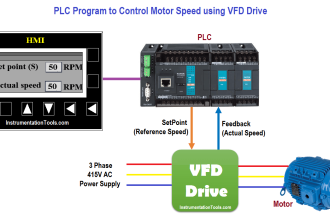
Implement the logic in PLC for motors operation based on time cycle using ladder diagram language.

Problem Diagram

PLC Motor Working based on time cycle

Problem Solution

Total 3 motors are used in this logic. Each motor should run for a total of 15 seconds duration.

For the first 5 sec. time duration the previous motor should also run along with the first motor. For next 5 sec. first motor should run alone and then second motor should be ON for next 15 sec.

The ON/OFF sequence of all three motors should be as per table given below. The sequence should continue till start input is present. When start input is switched OFF the sequence should stop.

Motors ON/OFF Sequence Table

PLC Motor Sequence Table

List of inputs/outputs

List of inputs

  • START PB :- I0.0
  • STOP PB :- I0.1

List of outputs

  • Motor 1(M1) :- Q0.0
  • Motor 2(M2) :- Q0.1
  • Motor 3(M3) :- Q0.2

M memory

  • Cycle ON :- M0.0
  • Relay coil :- M10.0

PLC Program for motors operation based on a time cycle

PLC Program for Motor Sequence Operation
PLC Motor Operation
PLC START PB
PLC STOP PB
PLC Motor Sequence

Program Description

For this application we used S7-300 PLC and TIA portal software for programming.

Network 1:

Cycle can be started by pressing START PB (I0.0) and can be stopped by pressing STOP PB (I0.1).M0.0 is cycle ON bit.

Network 2:

When cycle is ON, Main timer of 30s will start. Timer will turn OFF automatically after 30 sec by its own output (DB3.DBX6.0) or we can use relay coil (M10.0).

Network 3:

If main actual time is less or equal than 15sec, motor 1 (Q0.0) will remain ON.

Network 4:

If actual time is greater or equal than 10 sec and less or equal than 25sec, motor 2 (Q0.1) will remain ON.

Network 5:

If actual time is either less or equal 5sec or between 20sec and 30ses, motor 3 (Q0.2) will remain ON

Note :- Above application may be different from actual application. This example is only for explanation purpose only. We can implement this logic in other PLC also. This is simple concept of motor operation on given time cycle, we can use this concept in other examples also.

All parameters considered in example are for explanation purpose only, parameters may be different in actual applications. Also all interlocks are not considered in the application.

Result

PLC Program for Motor Operation based on Time Cycle Sequence

Author: Bhavesh

If you liked this article, then please subscribe to our YouTube Channel for PLC and SCADA video tutorials.

You can also follow us on Facebook and Twitter to receive daily updates.

Read Next:

  • Raw Counts to Engineering Units
  • Motor Operation from Local Control Panel
  • PLC Application for Stamping Operation
  • Web-based SCADA HMI Software
  • Setpoints and Alarms in Control System
Don't Miss Our Updates
Be the first to get exclusive content straight to your email.
We promise not to spam you. You can unsubscribe at any time.
Invalid email address
You've successfully subscribed !

Continue Reading

Step by Step Guidelines to Download Free Robotics Software
PLC Program for Automatic Mixing Control in a Tank
Normally-Closed Contacts for Stop Buttons
Siemens PLC Tia Portal – OB100 Start-up Organization Block
Schneider PLC Programming Example for Beginners
What are Trends in SCADA?
Share This Article
Facebook Whatsapp Whatsapp LinkedIn Copy Link
Share
1 Comment
  • Mohammad Mobin says:
    September 24, 2018 at 6:42 pm

    Dear Author,

    Kindly make your PLC programs in PLC S7 300 & S7 400 programming format, as most of the programs that you are showing are in S7 1200 format. I kindly request you to do the same or if you have already do then kindly let me know please. As most of the people dont have TIA portal for S7 1200.

    Thanks & Regards
    Mohammad Mobin

    Reply

Leave a Reply Cancel reply

Your email address will not be published. Required fields are marked *

Stay Connected

128.3kFollowersLike
69.1kFollowersFollow
210kSubscribersSubscribe
38kFollowersFollow

Categories

Explore More

How to Take Program Backup from Physical PLC? – Siemens PLC
PLC Output Types
Daily Alarm PLC Program using Real-Time Clock
Difference Between SCADA and HMI
How to Use Encode and Decode Instructions in PLC ?
How to Upload Siemens PLC Programs?
Free Schneider PLC Training – Automation Course
What is Resources Tab in the Siemens PLC?

Keep Learning

Remote Factory Acceptance Test

Remote Factory Acceptance Test

Creating Logic in Intouch Using Scripting

Create Logic with InTouch Scada using Scripting

Functional block diagram for analog alarms

PLC Logic for Analog Alarms using Functional Block Diagram

What is an Electromechanical Relay

Difference Between Solid State Relay and Electromechanical Relay

4-20mA Loop Power Supply Questions

4-20mA Loop Power Supply Questions and Answers

Pneumatic Circuit Design Using PLC - 2

PLC Pneumatic Circuit Control

PLC Program for Fishpond Water Level Monitoring System

PLC Program for Artificial Fishpond Water Level Monitoring System

Instruction List in PLC Programming

What is an Instruction List? – PLC Programming

Learn More

Calibration and Troubleshooting of Oxygen Analyzer

Calibration and Troubleshooting of Oxygen Analyzer

CPU Communication Ports in Siemens PLC

Types of CPU Communication Ports in Siemens PLC

spiral bourdon tube

Bellows, Diaphragms and Bourdon Tubes

Tank Gauging Measurement

Effect of Tank Design on Accuracy of Level Measurement

Emergency Shutdown Button Installation (ESD)

Understanding Emergency Shutdown Button Installation (ESD)

Process Plant Risk and Safety Management

Safety Roles & Responsibilities of Process Engineering (Detail Design)

caliper metrology tool

An Overview of Metrology Tools for CNC Machining

Common Valve Abbreviations

Common Valve Abbreviations in US Engineering Drawings

Menu

  • About
  • Privacy Policy
  • Copyright

Quick Links

  • Learn PLC
  • Helping Hand
  • Part Time Job

YouTube Subscribe

Follow US
All rights reserved. Reproduction in whole or in part without written permission is prohibited.
Welcome Back!

Sign in to your account

Username or Email Address
Password

Lost your password?