In a water treatment plant, there are majorly three types of systems – sewage water treatment, normal water treatment, and effluent treatment. Be it any system, one thing I have noticed common in them is the screen graphic design plays a very important role in them.
Typical HMI Screen Design
This is because the information is vast, records are important, logging activity is important, there are numerous instruments, and process flow showing is also important. So, graphic screen design, especially HMI, plays a very important role for programmers. In this post, we will see typical HMI screen designs for water treatment plants.
Water Treatment Plant
Let us have a look at each factor one by one:
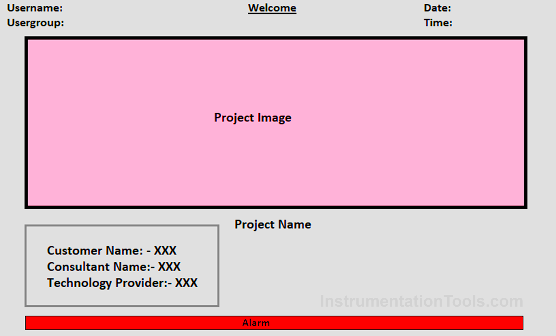
Welcome screen
This screen is common in all industrial systems, not only in water treatment. So, programmers must design this screen properly. Do not take very bright colors which trouble eyes for the background; standard colors are white, gray, light blue, or light brown.
Because HMI screens are small, if you also want to insert buttons in the header and footer, then choose the color that matches the colors of the buttons. Then, on the screen, insert details like project name, client name, consultant name if any, a photo of the system, and your company name.
Refer to the below image for a sample. Also, maintain the following details on all the screens – date, time, username, user group, and alarm banner.
Main Menu or Header-Footer Navigation
This is an HMI screen that needs very special attention in any system. An operator, just like our mobile phone, requires a screen or touch where he may be able to access all the main buttons for further operation.
So, be it a header footer or a screen with all the buttons, the following ones are usually required –
- IO status,
- auto mode (if plant operation is in either auto or manual mode),
- manual mode,
- reset,
- login,
- logout,
- engineering settings,
- P&ID,
- system architecture,
- configuration,
- trends,
- alarms, and
- audit trail.
Each button should have a corresponding security level for access.
IO Status
This HMI screen is also a common one found in all industrial applications. When you click this button, give a popup navigating to the four options – digital inputs, digital outputs, analog inputs, and analog outputs.
Each of these screens should have the following information –
- channel name
- channel description
- status
- unit (in the case of analog IO)
- simulation button (for each DI and AI)
The simulation button should only be accessible to higher-level group users for safety.
Auto Mode / Manual Mode
These buttons should have two actions. In one action, if no mode is currently selected in the plant, then this mode can be selected by navigating to the corresponding screen.
In the second action, if manual mode is already selected, then this button should not be accessible. An access denied popup should be shown immediately in this case. The same case works for auto mode and vice-versa. This alerts the operator that manual mode/auto mode is already running in the plant.
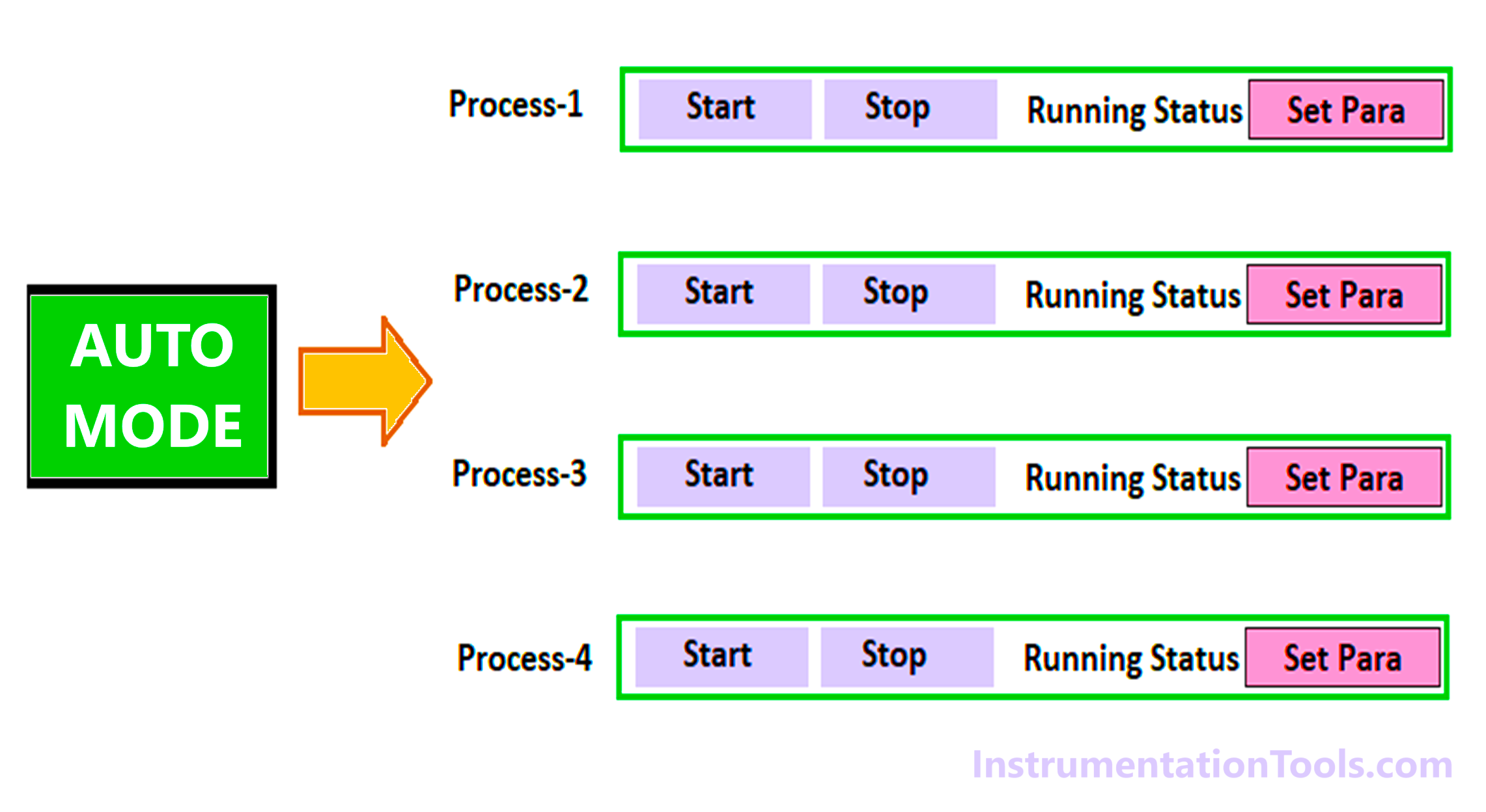
Now, in a water treatment plant, there are many sub-processes for a single plant. So, when auto mode is clicked, the below architectural designs are best preferred for easy operation.
When the whole plant has a single auto or manual mode, then the auto mode can be divided into various processes with individual start and stop, showing running status and navigating to a set parameter screen. The modes can be reset by pressing the reset button in the main menu.
In the second design, instead of auto / manual mode in the main menu, the button can be replaced with the button-process selection. This is applicable in cases where individual processes can be operated in either auto or manual mode. That means the processes are independent of each other. The modes can be reset by pressing the reset button on the independent process screen.
Login / Logout
Make sure to make proper groups and users according to the hierarchy required by the customer. Maintain a password matrix sheet.
In that, assign specific tasks to the groups. Due to this, on any screen of the HMI, you will be able to decide what security level needs to be assigned to that button or set parameter.
Engineering Settings
This screen should be accessible only to higher-level authorities. All the critical settings should be present on these screens.
P&ID
Because water treatment plants have water flowing through various processes, the first thing to note is that arrows must be shown on the pipelines. This should happen with arrows blinking and visible only when the particular line is in flow.
This depicts the user whose process is in flow right now. Then, show all the IO’s, from and to process arrows with labels, tag the equipment ID of each IO, tanks, current status (running cycle name) of the process, utility line (like steam, air, or water), and color change of the IO symbols for various states like on-off-trip-deselected.
System architecture
The HMI screen shows the overall system architecture with linking between the main PLC CPU, IO modules, HMI, Ethernet switch, or any other communication protocol.
The links should change color to red or green depending on it’s network health. Also, show the status of the CPU or modules like whether it is running, or at fault.
Configuration
As HMI is hardware, it should include a screen that can be accessible only to higher levels, for changing the configuration of the HMI like date and time, network settings, touch settings, etc.
Trends
Include a screen for showing the trends or graphs of analog values. Keep in mind the memory consumption of the HMI for assigning proper trend memory.
Alarms
Include a screen for showing the current alarm list and alarm history. Keep in mind the memory consumption of the HMI for assigning proper alarm memory.
Alarm memory is used to back up the alarms in case of a power outage and the total number of alarm records that it can store.
Audit Trail
Include a screen for showing the audit trail of the activities done by the user. Keep in mind the memory consumption of the HMI for assigning proper audit memory.
In this way, we saw a typical HMI screen design for a water treatment plant.
Read Next:
- Modbus Reading and Writing Data Basics
- Python in Industrial Automation System
- Wastewater Treatment Pumping Station
- PLC Program for Water Level Control Logic
- Create an Application in HMI with Tia Portal


I need Siemens SPPA-T3000 and Emerson Ovation DCS manual, Siemens S7-1400 and 1500 PLC manual