This article is about the configuration of input and output tags while establishing communication between SCADA and PLC using Siemens TIA portal.
Configuration of Input and Output Tags
As there is already an article published on communication here, I will explain to you to define input and output tags with an example.
Step 1:
Open the TIA portal. Create a new project. First, select the controller and then select HMI.
Step 2:
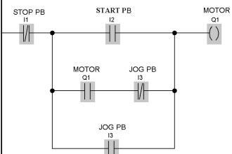
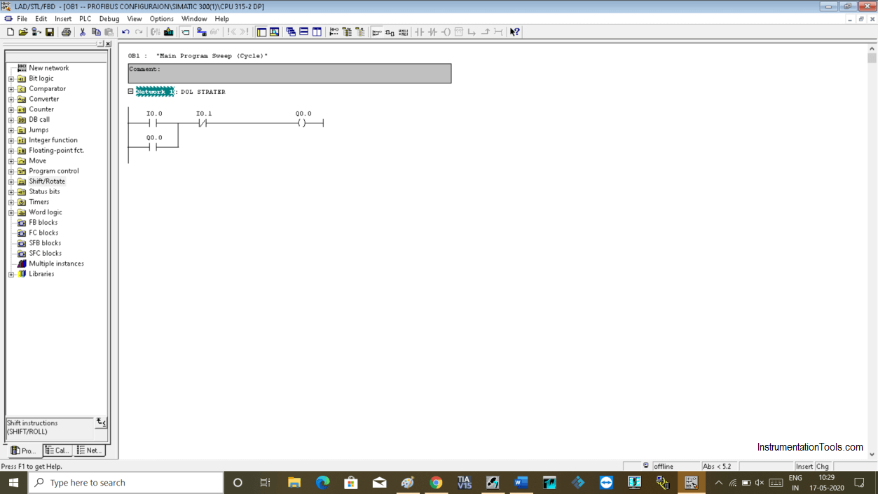
Here, for example, I have created a DOL starter. Have a look into the below window.
Step 3:
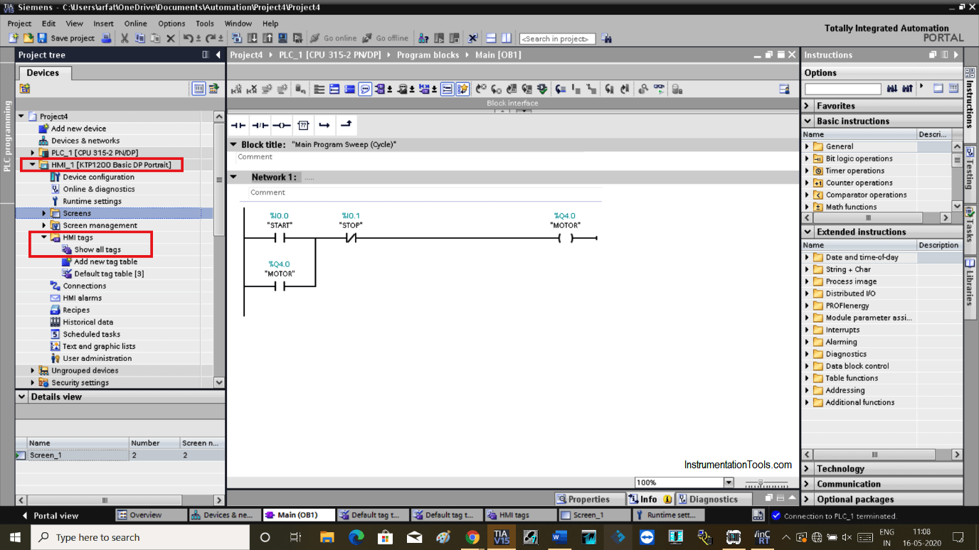
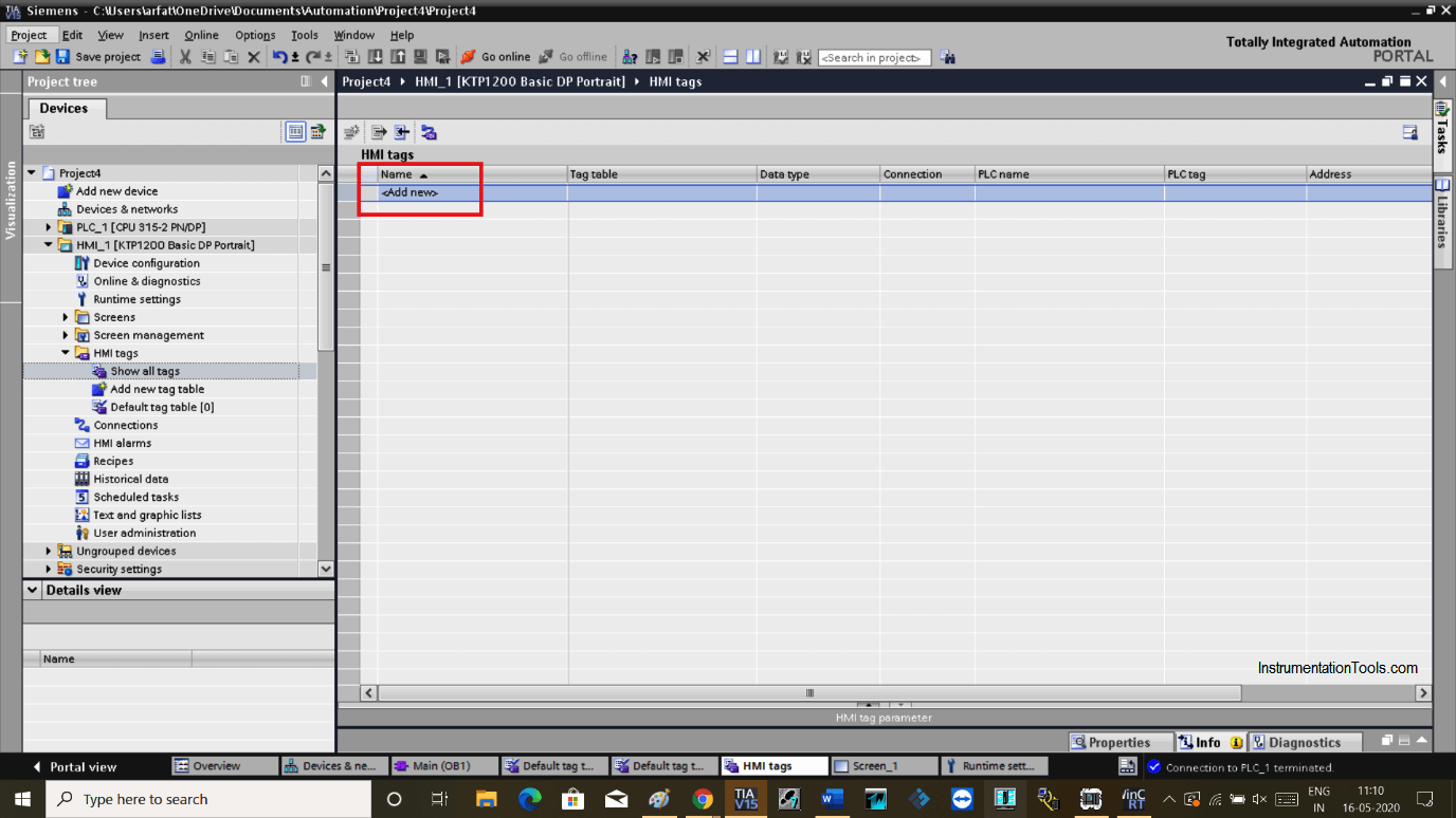
Now, on the left-hand side expand the “HMI” option as shown in the below window.
In the “HMI tag” section double click on “show all tags”.
Step 4:
The following window will open. Double click on “ add new” to add tag name.
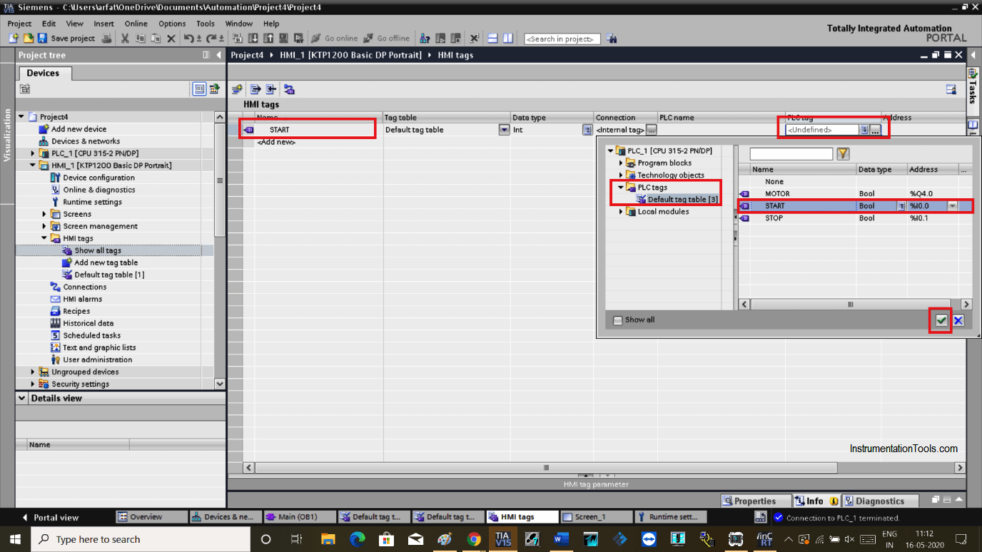
Step 5:
Add the name of the tags, as I have used START, STOP, MOTOR in PLC program.
Expand the “PLC tag” section. Choose “PLC tags” and double click on the “default tag table”. Choose START as shown in the below window. Hit the right checkmark to add to the HMI tag table.
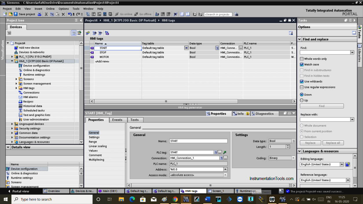
Step 6:
Again click on “add new” and do follow the same step as above to add STOP and MOTOR in the list and save the project.
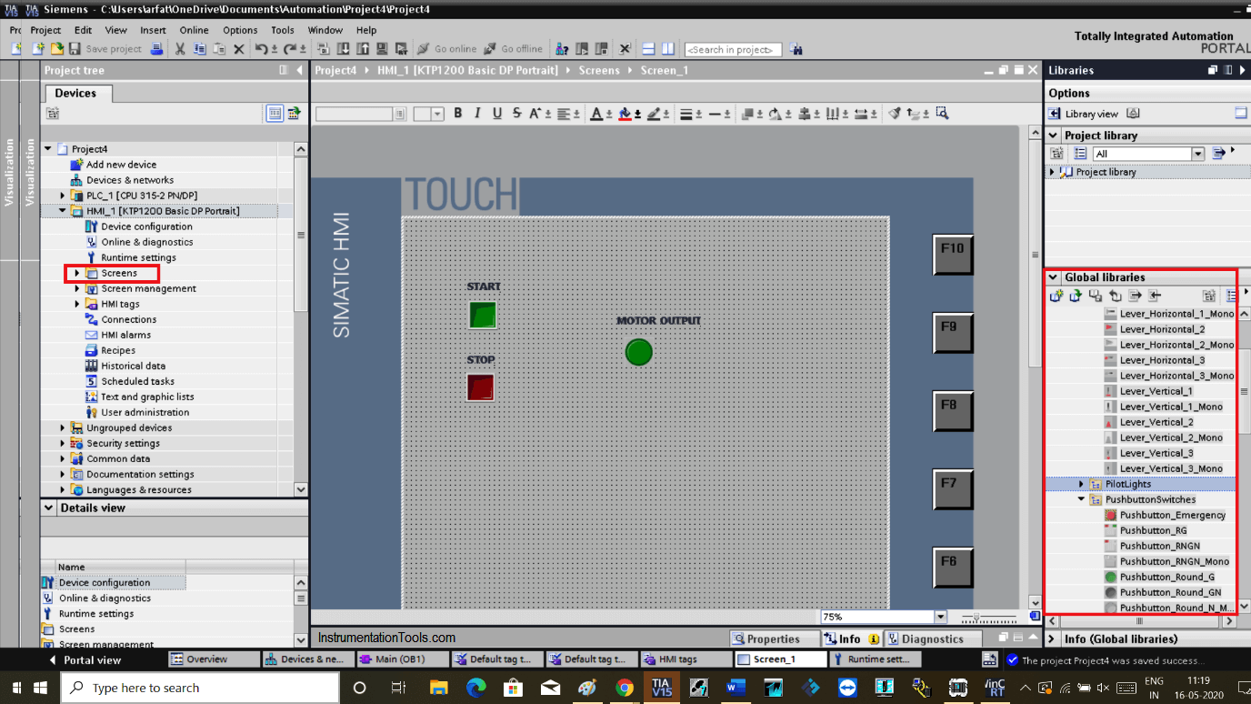
Step 7:
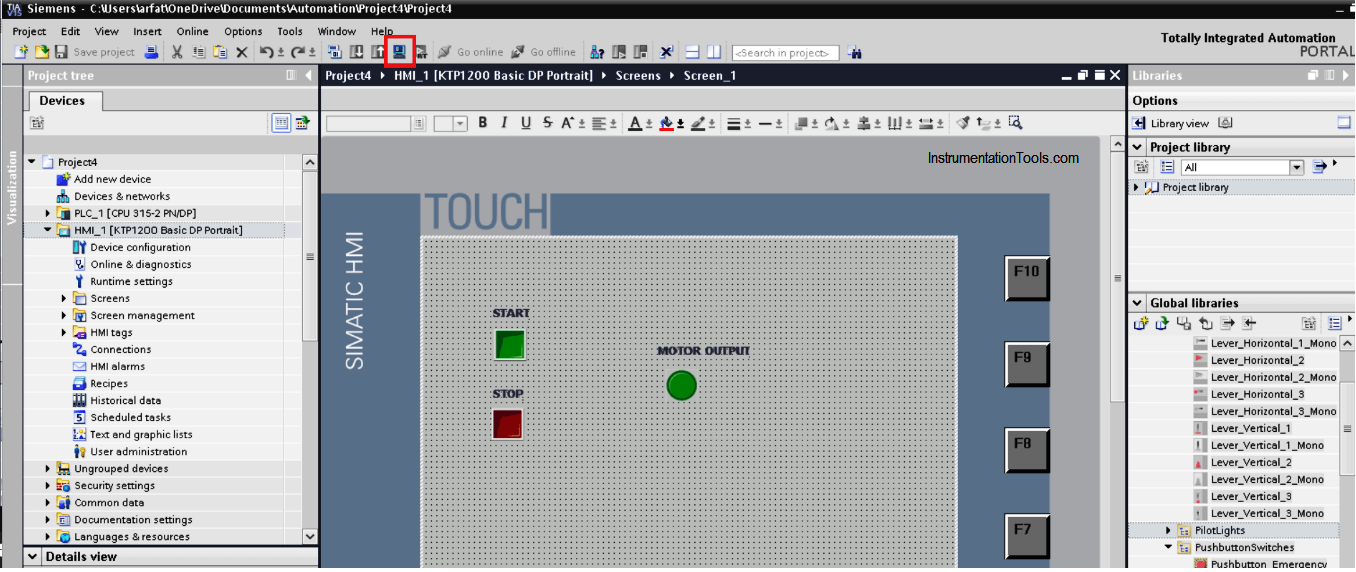
Now, Open HMI screen. Add Two pushbutton and one motor lamp indication from the right-hand side library as shown in the below window.
Step 8:
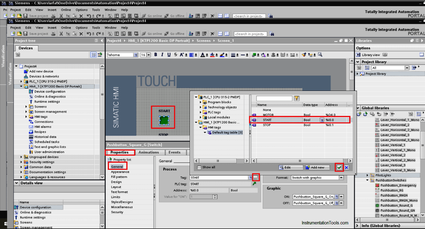
Hit double click on the START push button. In properties tab select “general”.
Expand tag as shown in the below window and choose START and hit the right checkmark. This will add PLC tag to HMI START pushbutton.
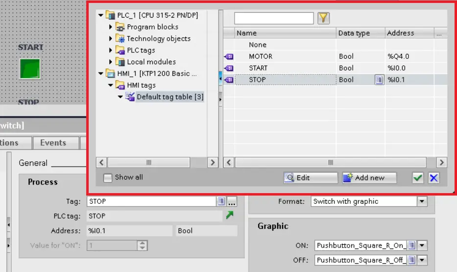
Step 9:
Do follow the same step to add STOP and MOTOR as shown in the below window.
Step 10:
Click on the simulate icon as shown in red square.
Also, simulate the plc program.
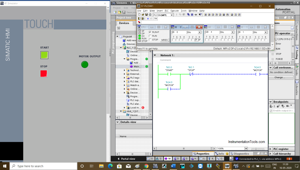
Step 11:
Test the logic. When START is ON output will ON.
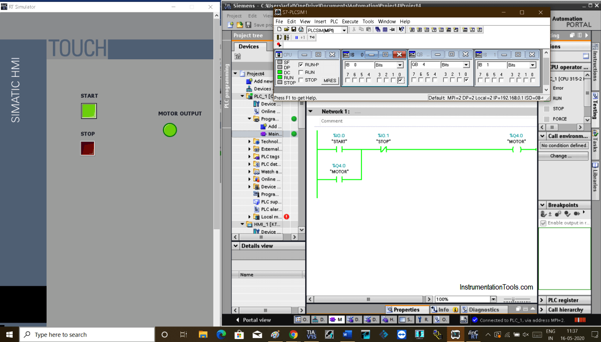
Step 12:
Pressing STOP will STOP the motor. To turn this facility ON and OFF from HMI simply replace memory bit or add in parallel with the program.
Author: Suhel Patel
If you liked this article, then please subscribe to our YouTube Channel for PLC and SCADA video tutorials.
You can also follow us on Facebook and Twitter to receive daily updates.
Read Next:
- Troubleshoot PLC Program
- Create Logic with InTouch
- Siemens PLC Memory Structure
- Configuration of Profibus Network
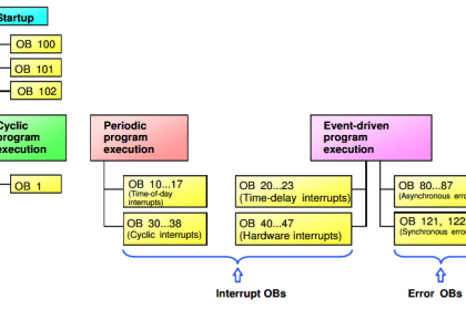
- Types of Interrupt in Tia Portal