The process of removing contaminants suspended solids and improving the quality of water in terms of oxygen content is known as water treatment.
There are majorly two types;
- Water Treatment Works (WTW)
- Wastewater Treatment Works (WwTW).
As its name implies the wastewater treatment treats the wastewaters from Industry, Agricultural, etc.
Broadly there are following types of Wastewater Treatment Works
- Sewage Treatment
- Industrial Wastewater Treatment
- Agricultural Wastewater Treatment
The water industry is going to be the most crucial in upcoming days seeing the scarcity of human usable water on earth.
Hence, it is going to be a key area for Instrumentation Engineers to automate the conventional, manually operated water treatment industry.
The environmental agencies provide chemical standards to industries based on which the quality of discharge water into water bodies like river, lakes etc. is maintained.
There are basically five stages in the wastewater treatment cycle.
- Preliminary Treatment
- Primary Treatment
- Secondary Treatment
- Tertiary Treatment
- Sludge Treatment
Among all the above treatment stages, there is ‘n’ number of processes that are automated and operated without human intervention.
The Instrumentation Engineers play a key role in automating these processes using various components like PLC, DCS, SCADA, and HMI’s.
Hence, understanding the processes in the wastewater treatment industry is prime important to run the plant without any human interventions and also by abiding by the rules and regulations provided by environmental agencies.
One of the key processes in Wastewater Treatment is Pumping Station. We shall now look into this process in detail from an Instrumentation Engineer perspective.
Pumping Station
In wastewater treatment plant, pumping stations are used to distribute, divert, stop or stabilize the water flow.
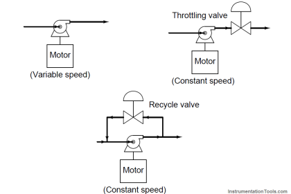
The typical pumping station consists of a tank, pumps (fixed speed drives or variable speed drives), level instruments, switches, and flow instruments.
The pumping station can be designed and implemented in any of the five treatment stages mentioned above.
Example 1:
In Preliminary Treatment, Pumping Station acts as a Storm Tank.
Storm Tank accumulates the water into the tank during the flood situation and releases it back to the main process treatment stream when the flood situation recovers.
Example 2:
In Sludge Treatment, Pumping Station acts as Sludge Holding Tank.
Sludge Holding Tank accumulate the Sludge for treatment. The treatment includes processes like removing excess water or chemical treatment etc.
Once the treatment is finished the accumulated sludge is pumped back to the discharge area for compost and other purposes.
Process Diagram
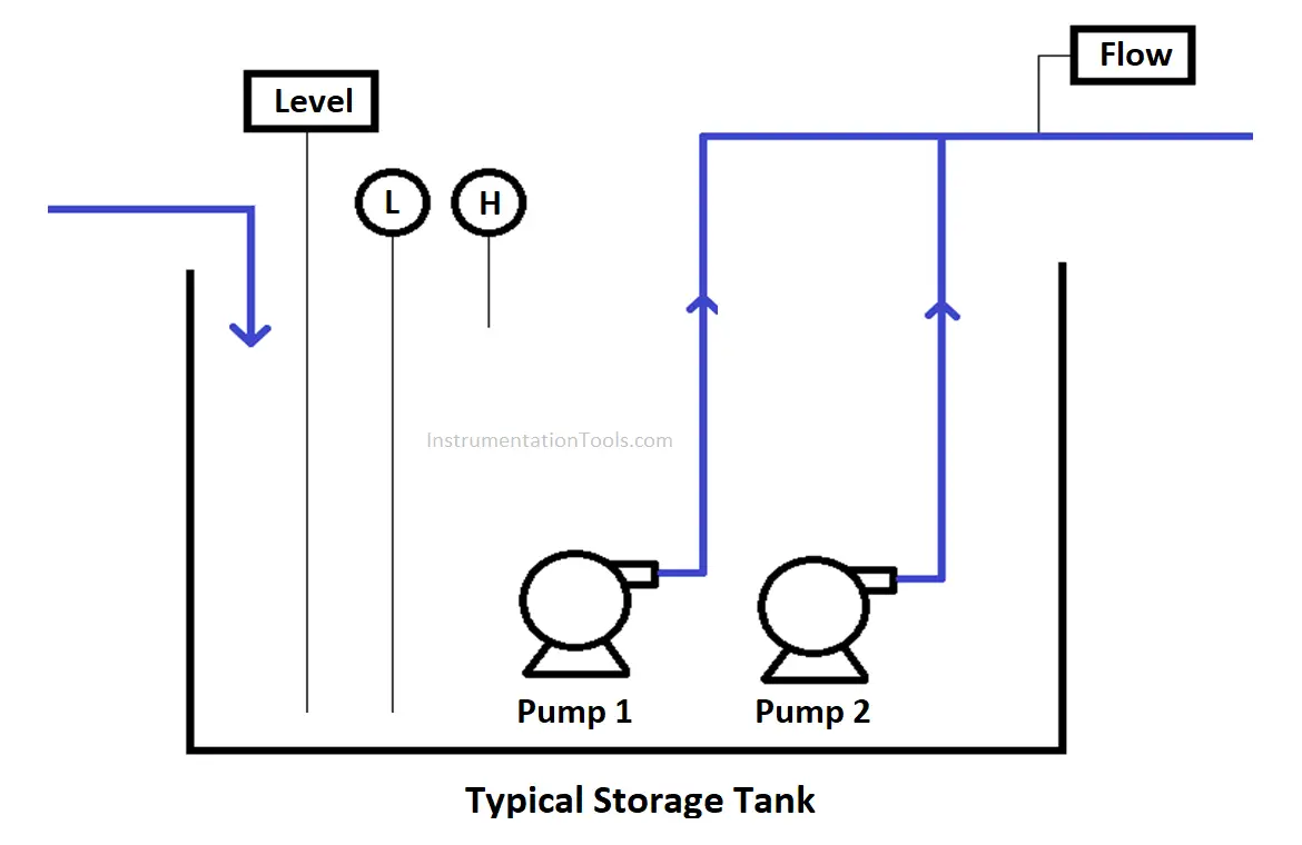
As stated above the Pumping Station consists of a tank (size is site-specific), pumps (drive types, number of drives is process specific), and level flow instrumentation (level or flow control is process specific).
We shall now study a typical pumping station consisting of a tank, 2 fixed-speed drives, level instrument, level switches, and flow instrument.
Level based Control of Pumping Station
The level instrument measures the level in the storage tank. Pump 1 & Pump 2 are fixed speed drives operating in Duty / Standby mode i.e. whenever the duty pump fails the standby pump shall be operational.
The flow instrument measures the outlet flow from the duty pump.
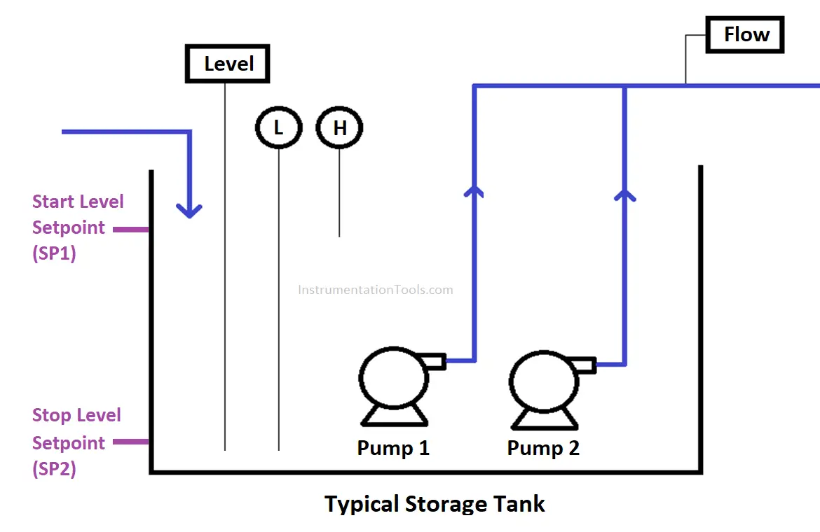
Storage Tank Auto Operation
- When the level in the storage tank goes above Start Level Setpoint (SP1), the Duty Pump shall start running.
- The pump shall run at a fixed speed to pump the process fluid out of the pumping station.
- If the level in the storage tank goes below Stop Level Setpoint (SP2), the Duty Pump shall stop until the level again reaches the Start Level Setpoint (SP1).
- The pumps are process interlocked with a Low-Level Switch.
- The operator can visualize the Outlet flow & Storage Tank level using process values displayed on HMI / SCADA.
The above scenario is typical Level based control of Pumping Station.
There are ‘n’ number of scenarios that can be designed using a typical pumping station as per process requirement.
Now we will look into another scenario.
Level Flow Cascade Control Pumping Station
The level instrument measures the level in storage tank. The Pump 1 & Pump 2 are variable speed drives operating in Duty / Standby mode i.e. whenever duty pump fails the standby pump shall be operational.
The flow instrument measures the outlet flow from the duty pump and controls the speed of the pump using a Proportional Controller (P).
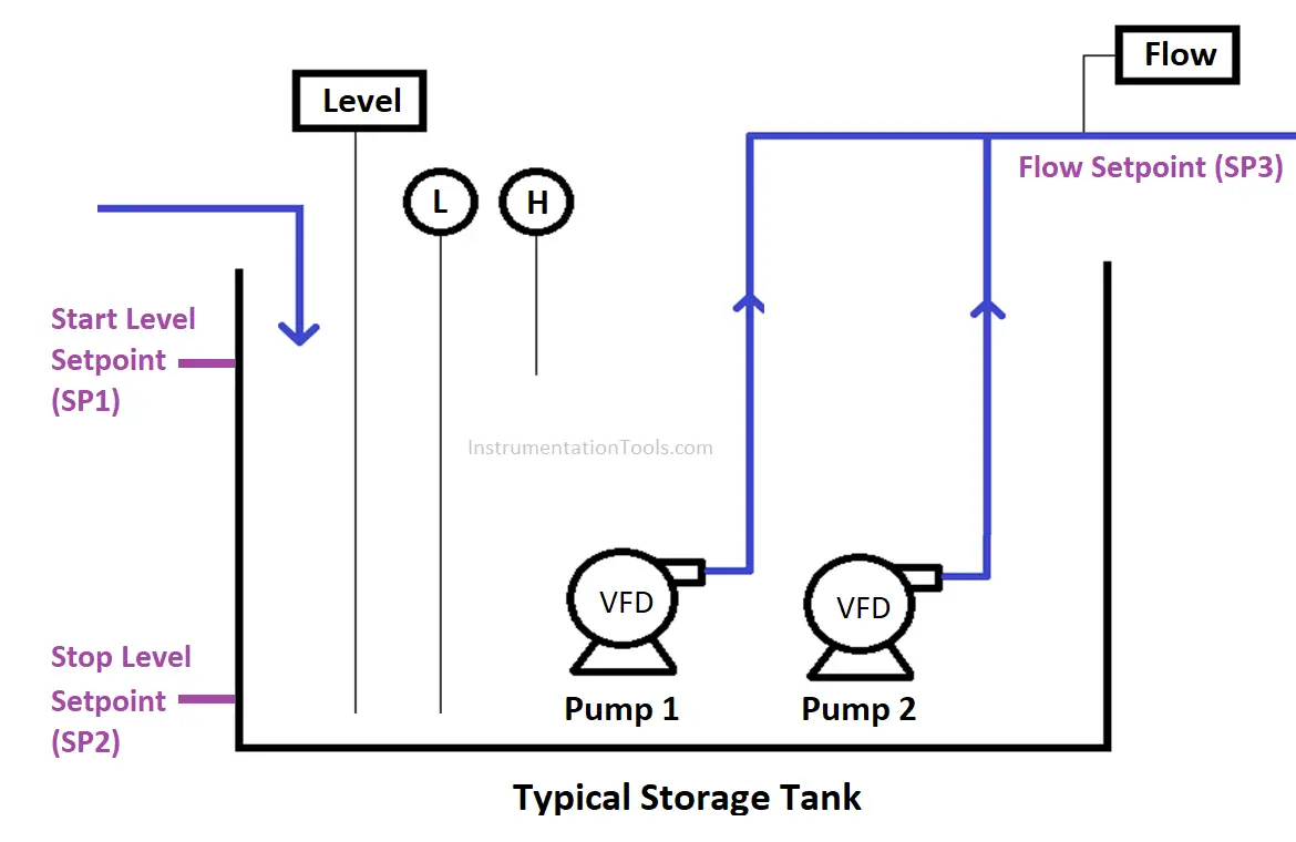
Storage Tank Auto Operation
- When the level in the storage tank goes above Start Level Setpoint (SP1), the Duty Pump shall start running.
- The speed of the pump shall vary proportionally to the Flow Setpoint (SP3) entered by the operator at HMI / SCADA.
- If the level in the storage tank goes below Stop Level Setpoint (SP2), the Duty Pump shall stop until the level again reaches the Start Level Setpoint (SP1).
- The pumps are process interlocked with Low-Level Switch & Low Flow measured by Flow Instrument.
- The operator can visualize the Outlet flow & Storage Tank level using process values displayed on HMI / SCADA.
Conclusion
We understood the basic operation of a typical pumping station along with two scenarios. It’s up to Design Engineer to design the process as per site requirement.
The Automation Engineer then automates the proposed process using PLC, DCS, SCADA, and HMI’s to operate the Plant with minimal human intervention.
Author: NMG
If you liked this article, then please subscribe to our YouTube Channel for Instrumentation, Electrical, PLC, and SCADA video tutorials.
You can also follow us on Facebook and Twitter to receive daily updates.
Read Next: