The first industrial programmable logic controller (PLC) was manufactured by the Modicon company in the United States, and very soon after the development of this revolutionary control computer that same manufacturer developed a digital communication network called Modbus designed to allow multiple Modicon PLCs to communicate data between each other over simple two- or three-conductor network cables. The development of Modbus happened in 1979, and for better or for worse this same communication protocol is still in widespread use at the time of this writing.
Modbus Protocol
This module introduces the Modbus protocol along with practical applications for its use. Important concepts related to Modbus include digital versus analog signaling, digital memory reading versus writing, memory addresses, serial protocols, the OSI Reference model, master versus slave network devices, data frames, error checking, encapsulation, and digital codes.
Here are some good questions to ask yourself while studying this subject:
- What is the purpose of a VFD?
- What is the purpose of a PLC?
- How is a PLC able to differentiate between different Modbus slave devices (e.g. VFDs) connected to it?
- What are some advantages and also disadvantages of using Modbus rather than analog signals for applications such as electric motor control?
- How does Modbus relate to various serial data protocols such as EIA/TIA-232?
- What are some of the limitations of Modbus inherent to its data frame format?
- How does ASCII differ from RTU in Modbus communications?
- How is encapsulation (sometimes) used in Modbus communications?
- How is it possible to communicate data longer than 16 bits (e.g. 32-bit floating-point values) in Modbus?
- What does it mean to say that Modbus is a “layer-7” protocol?
- How are Modbus data registers addressed within the target device?
Modbus Write One Register Data Exchange
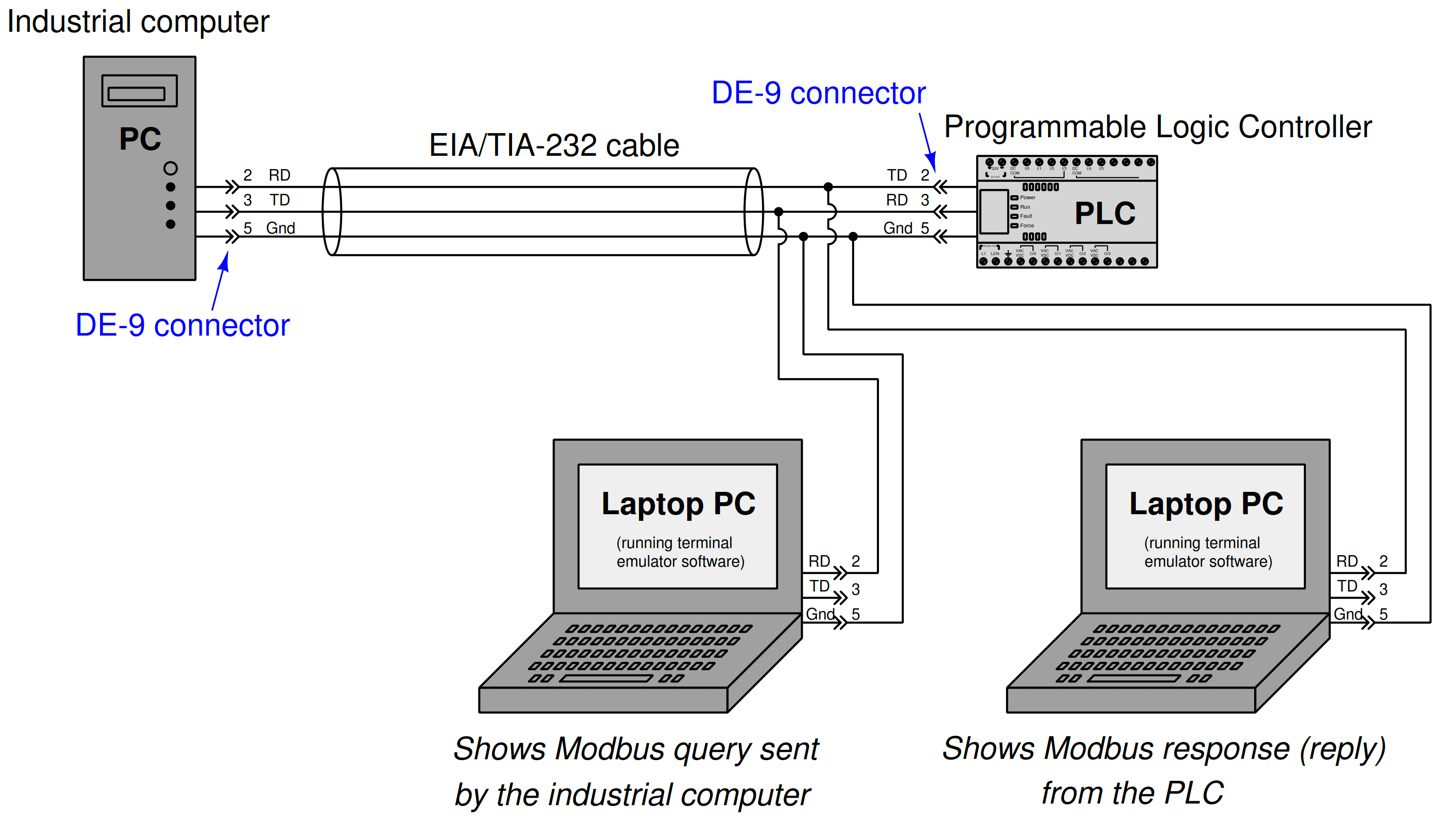
In the following system, an industrial computer sends a Modbus query to a programmable logic controller (PLC), which in turn replies with a Modbus response.
Both devices use Modbus ASCII to communicate, which allows us to use a pair of portable laptop computers to display each message in human-readable form:
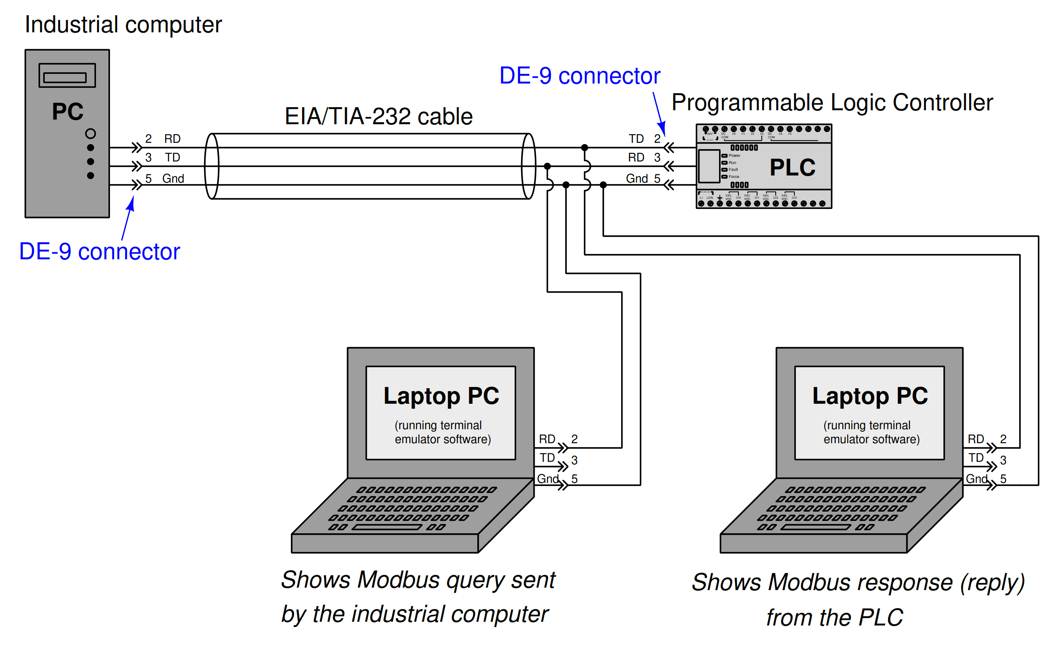
ASCII message sent by the industrial computer = :050610010200E2
ASCII message sent in response by the PLC = :050610010200E2
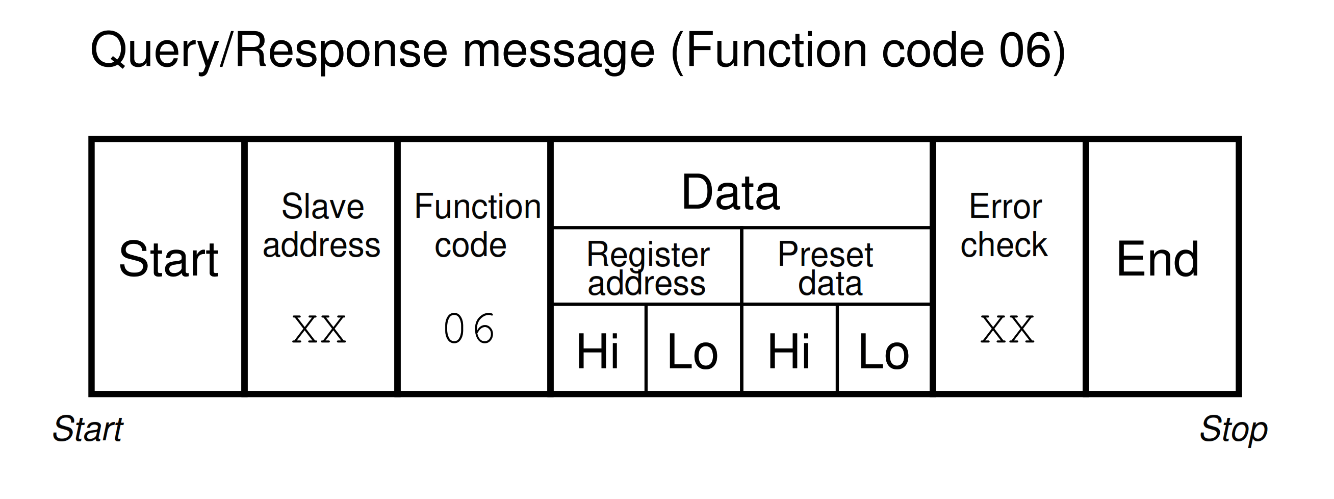
Analysis of Modbus query : 05 06 1001 0200 E2
- : is the starting character
- 05 is the slave address of the PLC
- 06 is the function code (06 = “Write One Register”)
- 1001 is the register’s relative address (relative address 0x1001 = 4097 decimal = absolute address 44098 decimal)
- 0200 is the data to be written to register 44098
- E2 is the message checksum (LRC)
The PLC’s response to this message is to simply echo it verbatim so that the industrial computer will be able to verify its receipt.
Modbus Read Register Data Exchange
In the following system, an industrial computer sends a Modbus query to a programmable logic controller (PLC), which in turn replies with a Modbus response.
Both devices use Modbus ASCII to communicate, which allows us to use a pair of portable laptop/computers to display each message in human-readable form:
ASCII message sent by the industrial computer = :050310000002E6
ASCII message sent in response by the PLC = :050304FF0600648B
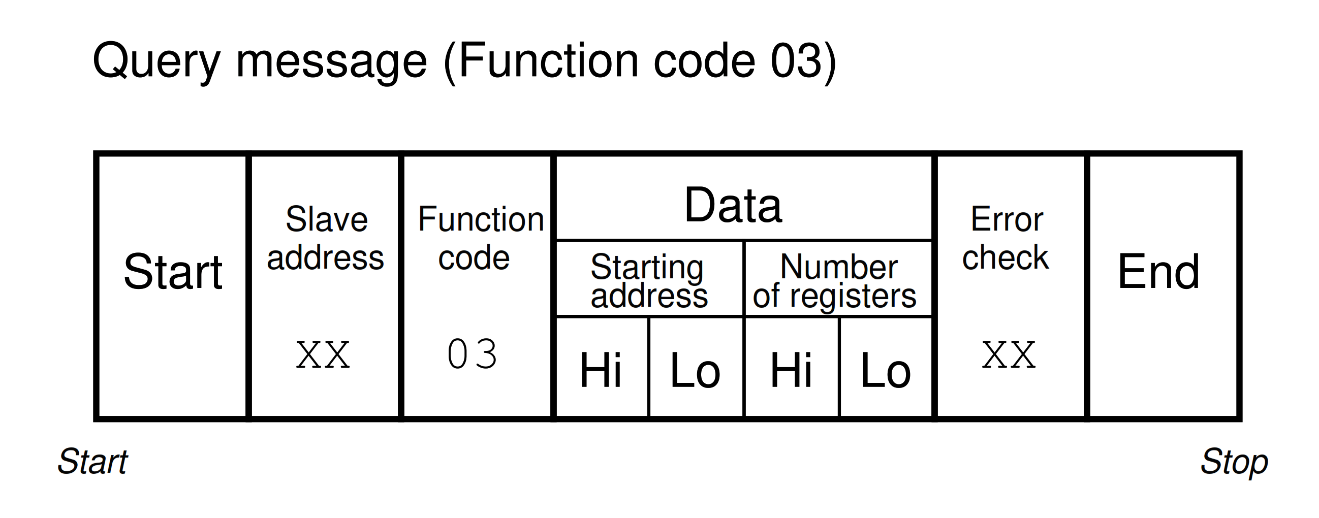
Analysis of modbus query : 05 03 1000 0002 E6
- : is the starting character
- 05 is the slave address of the PLC
- 03 is the function code (03 = “Read Register”)
- 1000 is the starting address (relative address 0x1000 = 4096 decimal = absolute address 44097 decimal)
- 0002 is the number of 16-bit registers to be read (two)
- E6 is the message checksum (LRC)
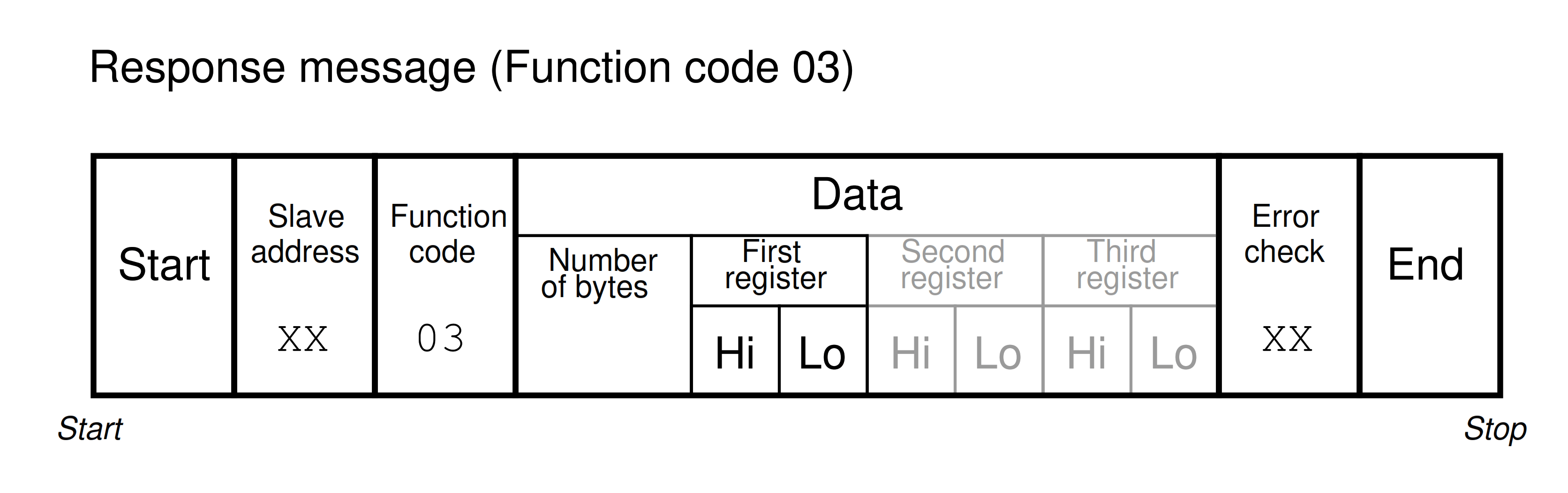
Analysis of modbus response : 05 03 04 FF06 0064 8B
- : is the starting character
- 05 is the slave address of the PLC
- 03 is the function code (03 = “Read Register”)
- 04 is the number of bytes returned (four bytes = two 16-bit registers)
- FF06 is the value stored in register 44097
- 0064 is the value stored in register 44098
- 8B is the message checksum (LRC)
© 2019-2021 by Tony R. Kuphaldt – under the terms and conditions of the Creative Commons Attribution 4.0 International Public License