Relays are essential for automation systems and for controlling loads. Also, relays are the best way for galvanic insulation between high and low-voltage portions of a circuit.
There are hundreds of different relay types. Let’s find out first how a relay operates.
Basic Relay Operation

The Contacts
Before extending to the various types of relays, i will first explain what and how the basic relay operates. Each relay has two mechanical parts inside.
The first one is the contact(s) of the relay. The contacts operates similarly to the contacts of a simple switch or pushbutton. You should consider the contacts as a pair of metals like the following diagram:

Contact No & NC
The two terminals operates as a switch. When the contacts are ‘in contact’ then the current flows from Terminal 1 to Terminal 2. There are two types of contacts: the NO and the NC.
NO stands for Normal Open contact, while NC stands for Normal Closed contact. The Normal Open is a contact like the one showed in the previous illustration. When the contact is still, then no current flows through it (because it is an OPEN circuit).
On the other hand, a Normal Closed contact allows the current to flow when the contact is still. Bellow i illustrate both of these contacts:

You may notice that the NC contact is turned upside-down compared to the NO contact. This is done in purpose. This way, both contacts (NO and NC) will change state if a force is applied to the left metal heading from UP to DOWN.
The following animation shows how a NO contact operates by lighting a light bulb:

As for the NC contacts, it works exactly opposite as the NO contacts. Look the following animation:

A combination of contacts
A relay may have a combination of the above contacts. Look at the following illustration

In this case, there is a 3rd terminal called “COMMON”. The NO and NC contacts are referred to the COMMON terminal. Between the NC and the NO contact, there is no contact at any time!
The following animation shows how this pair operates:

And Who defines the NORMAL state?
OK, we have the NORMAL open and NORMAL closed contact. But which state is considered as NORMAL? Going one step closer to the relay operation, we find the spring.
This spring defines the NORMAL position of the COMMON contact. If you see the above 3 animations, you will notice that one time an F force is applied to the COMMON terminal, and the other time there is no force applied. Well, this is actually wrong.
There is indeed another force that pulls the contact towards UP and this force is applied ALL the time. This force comes from the spring. Look the following image:

Now you can see who is pulling the COMMON terminal UP all the time. So the spring defines what is the NORMAL state, and thus defines which contact is the NORMAL OPEN and which the NORMAL CLOSED.
In other words, the NORMAL state is defined as the state that there is NO other force applied to the COMMON terminal except the one from the spring.
The last part – WHO moves the common contact of the relay?
This is the last part of the relay operation. The device that forces the terminal to move, is actually an electromagnet! A coil is placed right under the contact.
When current is flown through this coil, a magnetism is created. This magnetism can overcome the force of the spring and can pull the contact towards it, thus it changes it’s position! And due to the fact that the contact is usually a small piece of metal not capable to be pulled by the electromagnet, another piece of metal is attached to the common.
This piece of metal is so called “Armature”. Following is (at last) the complete illustration of the basic relay:

Now, imagine that someone wants to control a 220Volts 1 K-Watt load with a command that comes from a 5 Volts battery. A load-Relay should be used for this application.
The Coil of the relay is driven with the 5 Volts. The contacts from this relay (NO) will be connected in series with the power supply of the load.
Thus, the load will only operate when the relay is actuated. Our friend bellow will turn on an electric oven bare-handed!!!

Looking inside the relay
I used an octal-type relay. These relays are easy to open (either with screws or clips), and are big enough to have a clear view. So, here is the relay opened:

You can clearly see the common contact, the NO and NC contacts as well as the electromagnetic coil and the return-to-normal spring. The armature is the thick metal that the common contacts are fixed on it.
Relay Types
There are so many different types of relays, that it would be literally impossible for me to add them in this article.
Therefore, i will categorize the types of the relays in terms of:
1. Turn ON/OFF operation
2. Coil
3. Contacts
Category 1. Turn ON/OFF operation
Normal relays
There are basically two types of relays in this category. The first type is the normal on/off relay. This relay changes state as long as the electromagnet is actuated, and goes back into relax state when the electromagnet is not actuated any more.
This is the most common relay type and is used widely in automation.

Toggle relays
This type of relay operates just like a toggle flip flop. When the coil is once actuated, the relay will change state, and will remain in this state even if the coil in no more actuated.
It will only change state again on the next pulse that will actuate the coil. This is very handy in modern house lighting.
Having this relay instead of a switch, you can turn on and off the lights with one pushbutton. You press the pushbutton once and the lights are turned on. On the next pushbutton press, the lights are turned off.
Latching relays
This type of relay operates exactly like the R-S flip flop. It has two different coils instead of one. When the first coil is actuated, the relay goes to the SET position and it remains there no matter if this coil is kept actuated. It will only change state (to RESET position) only if the other coil is actuated.
This type of relay is widely used in applications where the state of the relay needs to be kept as is, even after a power failure or a restart.

Protective relays
I will distinguish this type of relays in two sub-types. The first sub-type is the current-leaking protective relay, and the other type is the overload protection relay.
a. Protective relays – current-leaking
Almost everyone knows these relays. They does not actually have an electromagnetic coil. Instead, they remain armed all the time. Two electromagnets are placed one opposite the other. Between them, there is the armature. This armature is magnetized from both electromagnets.
The first electromagnet is placed in series with the Phase, while the other is connected in series with the Neutral. If the current that flows through both electromagnets is equal, then the armature is kept in balance.
But if the current that flows through the second electromagnet is less than the current that flows through the first electromagnet, then the armature is pulled to the first electromagnet that has greater magnetic force! And how can this happen? Easy, if somehow an amount of current flows to the ground of the installation.

These relays can (and SHOULD) be found in every household electrical installation, right after the main switch. Look at the following illustration:

The light bulb is turned on because the magnetic power from both coils is equal. Now look what happens if “somehow”, the current on the neutral is less than the current on the phase.
The magnetic power of the electromagnets is not equal, thus the relay will cut the power supply and our friend will be saved. For safety reasons, if this happens, the relay can only be restored mechanically, if someone pulls the lever of the relay up again:

b. Protective relays – overload
Very common relays in motor applications, as well as in all electrical installations. These relays wave no electromagnetic coil to move the armature. Instead, they have a bimetallic strip that the current flows within.
The material and the thickness of this strip is carefully selected, so that it will be heated (and thus bended) above a specified current value.
When the bimetallic strip is bended, the relay will cut-off the power supply. For security reasons, the relay can only be restored mechanically by moving the lever by hand.

This is the basic idea of the overload protection relay figure below

If one line is overloaded, the bimetallic strip is overheated and thus it bends, breaking this way the contact. shown in below figure

It should also be mentioned that there is another kind of overload protection relays called “electromagnetic relay”. This operates exactly the same as the overload protection relay, but has inside also another electromagnet.
If this electromagnet is powered, then the relay will be forced to break connection, as if it was overheated. This functionality allow to check for faults and stop a motor to avoid any other problem, even if the motor itself is not overheated.
Temperature relays
These relays operates similarly to the overload protection relays above. The major difference is that the bi-metallic strip is not heated by the current that flows within the strip, but from an external factor.
This factor could be the ambient air, water temperature, another fluid refrigerator temperature etc. You may know these relays with another name… thermostats, used extensively in heating applications.

Another difference from the protection relays is that the temperature relays usually do not need an external mechanical movement to restore it’s state. The process is done automatically according to the temperature of the bimetallic strip.
Reed relays
You could imagine a reed relay like a relay without an electromagnet. The reed relay’s armature is actuated from any other external magnetic field. The reed relays can be found in door monitoring systems.
A permanent magnet is attached to a door, while the reed relay is right above the magnet. If the door opens, the state of the reed relay is changed. Another common application for reed relays is on the speed meters of the bicycles.
A permanent magnet is attached to the wheel of the bicycle, while the reed relay is fixed on the “fork” of the bike. Every time the wheel rotates and the magnet passes in front of the reed relay, it sends a pulse to a microcontroller.
Other relays
There are many other types of relays like the timers and the function relays, but they use some kind of circuitry to perform different actions. I will not go into these categories, as this article is only interested to the kind of relays that uses no other circuitry, only mechanical variations.
Category 2. Coil Actuation
Another type of relay categorization is the coil. In this category i separate the relays according to the way that their coil is powered to actuate the armature. So we have:
AC/DC relays
The coil can operate with either AC or DC voltage.
Neutral relays
These relays have the most common coil. The armature is actuated when current goes through the coil, regardless the polarity.
Biased Relays
This is a variation of the neutral relays. These kind of relays have exactly the same coil as the neutral relays, but they carry a permanent magnet on the armature. The polarization of the magnetic field of the coil depends on the polarity of the supply.
Therefore, the armature is actuated only if the polarity of the coils’ magnetic field is opposite to the polarity of the permanent magnet’s magnetic field. This way, the relay is actuated only if the coil is correctly biased.

Polarized relays
This kind of relays operates exactly the same as the biased relays. The only difference is that these relays does not have the permanent magnet, instead they have a diode in series to the coil. If the diode is correctly biased, the coil will have power and the armature will be actuated.
The difference that makes these two relay types different is that the biased relays will allow the current to flow through it’s coil, even it the relay is reverse-biased! Very important if someone wants to connect the coils of two or more relays in series.
Solid State Relays (SSR)
This is the modern type of relays. These relays does not have a coil, nor any other moving part, that’s why they are called Solid State. They are used for fast switching (up to several hundreds of Hz) and for controlling loads in explosive or harsh environments.
They have significantly more lifetime than the conventional relays, as their contacts will not corrode due to humidity, dust or other causes. Actually, they do not have contacts! Instead, a FET or a TRIAC is used to simulate the contacts. The major disadvantage is the price…
Category 3. The contacts
The third and last category is the contacts of the relays.
There are 3 major characteristics that distinguishes the relays:
1. The max voltage: This characteristic is determined by the gap that exists between the contacts, as well as the alloy that the the contact is made of. The higher the gap the higher the voltage that a relay can cut-off.
2. The max current: This characteristic is determined by the thickness of the contacts, as well as the alloy that the the contact is made of. The thicker the contacts the higher the current that a relay can handle.
3. The switching frequency: This characteristic is determined by the mechanical construction of the relay. The lighter the construction, the faster the switching.
4. The number of contacts:…Just the number of contacts.
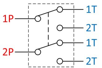
As far as the contact number is concerned, the relays (like the switches) comes with some kind of coding. The general code form is this:
xPyT
The ‘P’ stands for “POLES”. The ‘x’ is the number of “POLES” that a relay has. Thus, if a relay has 1 contact pair (POLE), the code would be SP as for Single Pole. For two contact pairs, it would be DP as for Double Pole. Above 2 contact pairs, the x gets the number of poles, eg for 3 poles it would be 3P etc etc.
The ‘T’ stands for “THROW” and ‘y’ is the number of “THROWS”. ‘y’ can be Single or Double. Single Throw (ST) means that there is only one NO or NC contact. Double Throw (DT) means that the relay has pairs of NO/NC contact.
Relay Symbols
The relay symbols are unlimited. Each manufacturer can make his own symbol for a specific relay that has different internal connections and characteristics, carrying out a specific task. I will illustrate the most basic types of relays:

Relay Characteristics
The things that characterizes a relay are the followings:

The coil voltage: This is the voltage that the coil can actuate the armature. This value should indicate also if the current is AC or DC
The coil current: This value indicates the current that the coil will draw when it is powered with the indicated coil voltage. Very important characteristic to take into account when designing the driver of the relay. The current that goes through the driver must be enough to actuate the armature.
The off-voltage: This characteristic shows the minimum voltage that the armature is pulled by the electromagnet. If the voltage goes bellow this value, the spring will overcome the magnetic force and the relay will change state.
The number/type of contacts: Is it an SPST? An DPST? DPDT? Or what?
The power for the contacts: This characteristic indicates the maximum power that the contacts can handle. Some manufacturers will use the voltage and the amperes, some others the voltage and the kilo-watts, while some others will indicate all three values.
The operating temperature: The temperature that the relay can operate without problems
Switching frequency: The maximum make-break frequency
The package: Last but not least is the package. Some packages (like the octal type) comes with an appropriate base, while some others are directly soldered/connected to the PCB/electric cabinet.
If you liked this article, then please subscribe to our YouTube Channel for PLC and SCADA video tutorials.
You can also follow us on Facebook and Twitter to receive daily updates.
Read Next:


Very good explanations on relays and their types. Keep it up.
I want more information
Need more info on SSR. thanx
i want information in deeply
Thank you
I don’t have a word for u sir, superb or I should say khatarnak nice….
Nice information about relay
Rocking info …
Good information about reley
Awesome Information, I would like to understand more about relay.
If you don’t mind, please send me your contact information.
That is really explainable, thank you so much
Excellent information with perfect explanation.