An induction motor is one of the best equipment that you can ever use in any factory but on the other hand and due to misuse, it could be very dangerous to all of your electric system and the other equipment.
Today we are going to discuss how the induction motors could be harmful and how to overcome these situations.
Relation Between Current and Voltage
As all of us know a voltage is directly proportional to current as (V = I*R) but in the case of constant power sourcing we will find that the supplied voltage is affected by any change in the amount of supplied current.
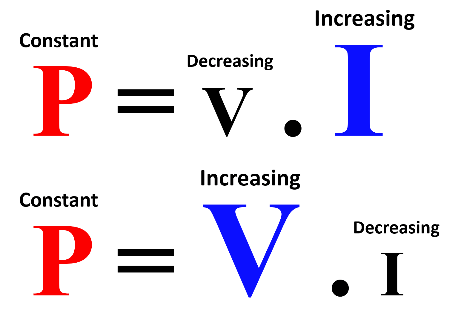
This means if a transformer supplies the electric system with constant power (P), the change of the electric load (Motors, actuators …) will affect the supplied voltage as (P = V*I).
So, in the case of high loads, we will find the system voltage will decrease and in the case of low loads, the system voltage will increase as shown in Fig (1).
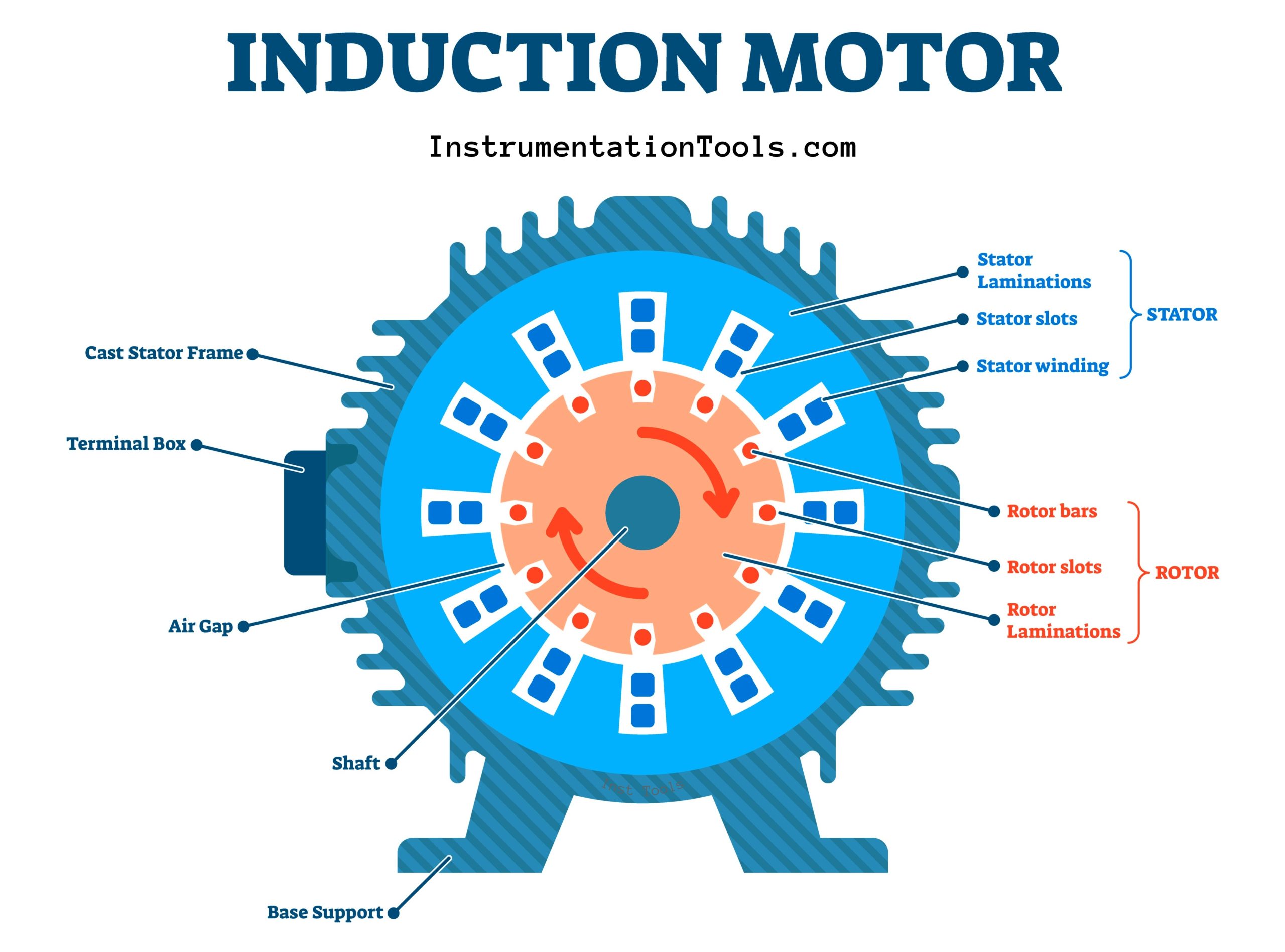
Induction Motor Operating as a Generator
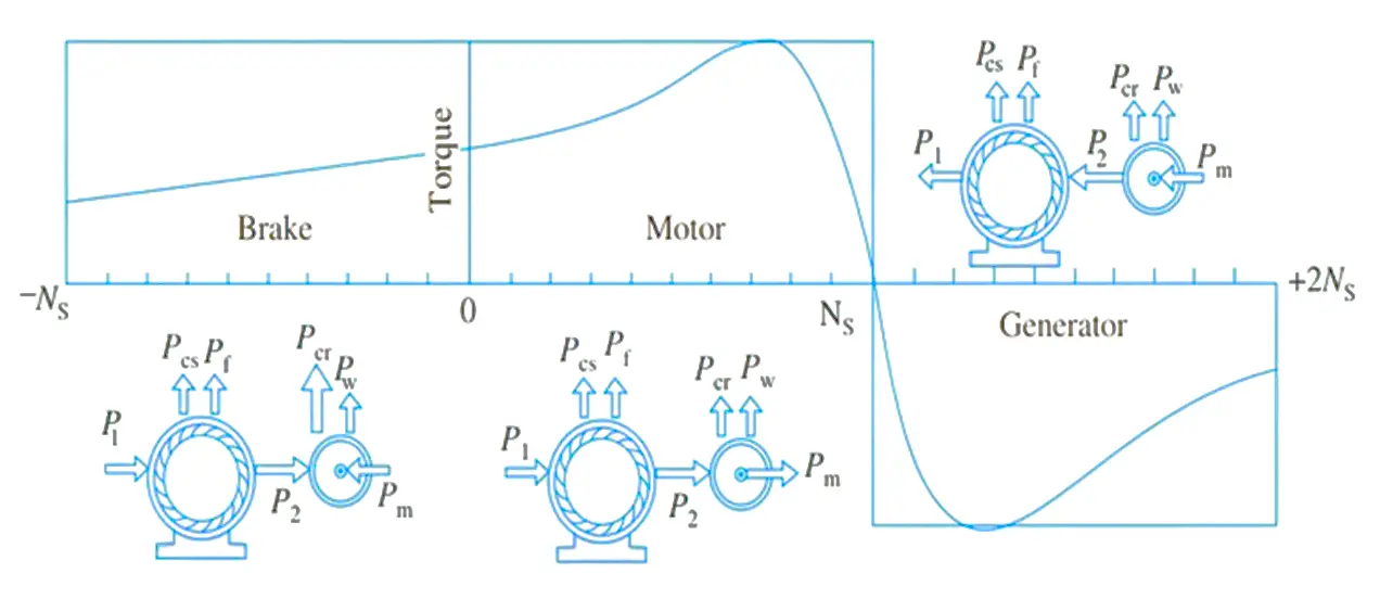
In the case of the immediate stoppage of an Induction Motor, the rotor will run faster than its synchronous speed, the motor will behave as a generator called an Induction generator.
It converts the stored mechanical energy (motor rotating inertia) to electrical energy and the stator releases this energy.
As soon as the power is disconnected from the stator windings (the stator magnetic field will stop), the rotor (magnetic field) speed will exceed its synchronous speed, then it will start delivering active power P to the 3-phase line. As shown in Fig. (2)
As a result of this situation, there will be Unnecessary Energy (current) in the power network which will cause an Overvoltage in the whole power supplied.
Of course, that will negatively affect all the system components and it could also make serious damage to the electric system.
Induction Motor Starting Current Vs. Undervoltage
An induction motor starting on full voltage (also known as across-the-line starting or direct online starting) has the undesirable effect of drawing five to ten times or more of motor full load current.
Usually, this starting current of the induction motor persists till the motor reaches close to its synchronous speed (rated speed).
Induction motors under starting conditions have deficient power factors of around 10-30%.
The combination of a large starting current and poor power factor will cause large voltage drops across the system impedances.
In most situations, the voltage sag that occurs across the MDB (Main Distribution Board) that supplies the power to your factory cannot be caused by starting one or two motors.
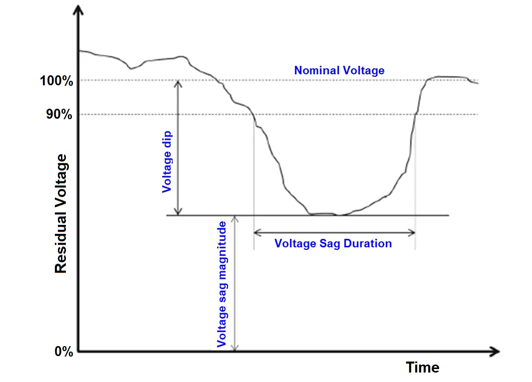
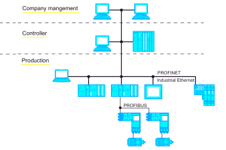
You may have a huge number of motors in your plant, and stating all of these motors together would defiantly cause the voltage sag in the electric network as shown in Fig. (3)
The significant voltage drop created by induction motor starting can cause two major types of problems:
- The starting motor itself may not be able to accelerate to its rated full speed due to low bus voltage. Remember that starting torque of the induction motor varies as the square of the applied voltage.
- The voltage sag created by the induction motor starting may cause lights to dim, contactors to drop out, variable frequency drives to shut down, digital devices to reset causing loss of data, etc.
How to Operate an Induction Motor Correctly
As we discussed above there are two major problems that are occurred due to the operation of an induction motor, these problems are:
- Supplied power Overvoltage due to the sudden stop of a group of induction motors.
- Voltage sag produced by induction motor starting current is one of the main causes of sensitive equipment dropout.
To overcome this kind of problem simply you have to start and stop all of the plant induction motors in a coordinated and organized manner.
Using the system logic and control elements (PLC programming), we can start the whole system step by step to ensure that every piece of equipment is operated in healthy conditions.
Also, the use of a motor starter is a must as it reduces the voltage sag depth and increases its duration.