Inst ToolsInst ToolsInst Tools
  • Courses
  • Automation
    • PLC
    • Control System
    • Safety System
    • Communication
    • Fire & Gas System
  • Instrumentation
    • Design
    • Pressure
    • Temperature
    • Flow
    • Level
    • Vibration
    • Analyzer
    • Control Valve
    • Switch
    • Calibration
    • Erection & Commissioning
  • Interview
    • Instrumentation
    • Electrical
    • Electronics
    • Practical
  • Q&A
    • Instrumentation
    • Control System
    • Electrical
    • Electronics
    • Analog Electronics
    • Digital Electronics
    • Power Electronics
    • Microprocessor
  • Request
Search
  • Books
  • Software
  • Projects
  • Process
  • Tools
  • Basics
  • Formula
  • Power Plant
  • Root Cause Analysis
  • Electrical Basics
  • Animation
  • Standards
  • 4-20 mA Course
  • Siemens PLC Course
Reading: Too Low Efficiency Torque Converter Elimination Attempt
Share
Font ResizerAa
Inst ToolsInst Tools
Font ResizerAa
  • Courses
  • Design
  • PLC
  • Interview
  • Control System
Search
  • Courses
  • Automation
    • PLC
    • Control System
    • Safety System
    • Communication
    • Fire & Gas System
  • Instrumentation
    • Design
    • Pressure
    • Temperature
    • Flow
    • Level
    • Vibration
    • Analyzer
    • Control Valve
    • Switch
    • Calibration
    • Erection & Commissioning
  • Interview
    • Instrumentation
    • Electrical
    • Electronics
    • Practical
  • Q&A
    • Instrumentation
    • Control System
    • Electrical
    • Electronics
    • Analog Electronics
    • Digital Electronics
    • Power Electronics
    • Microprocessor
  • Request
Follow US
All rights reserved. Reproduction in whole or in part without written permission is prohibited.
Inst Tools > Blog > Root Cause Analysis (RCA) > Too Low Efficiency Torque Converter Elimination Attempt

Too Low Efficiency Torque Converter Elimination Attempt

A 3.3 kV 450 kW, 1480 RPM 3 φ motor couples to a gearbox input shaft and output shaft to the hydraulic torque converter (HTC).

Last updated: September 28, 2022 2:51 pm
S Raghava Chari
Root Cause Analysis (RCA)
No Comments
Share
5 Min Read
SHARE

The below figure shows the above Carbomate feed to the urea reactor Plunger Pump A drive. Pump B of identical drive – not shown – is its hot standby.

Contents
Hasty DecisionCase Study takeaways

A 3.3 kV 450 kW, 1480 RPM 3 φ motor couples to a 1480:100 RPM gearbox input shaft, the GB output shaft to the hydraulic torque converter (HTC) input shaft.

The HTC output shaft coupled to the plunger pump to run it at set 40-100 RPM. The HTC efficiency averaged 25% at 40-RPM output speed and 30% at 90 RPM output speeds.

Plunger Pump Drive

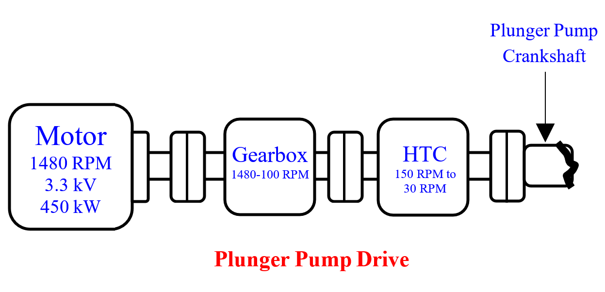
The torque convertor’s very low efficiency and the associated wasted power bothered the author. Hence, he wanted to remove it and directly couple the GB output shaft to the pump crankshaft and power the motor with an Electronic Variable Speed Drive (EVSD) to run the pump at 30-100 RPM.

An inexpensive bought-out pressure to the current converter would covert the existing speed controller’s 3-15 psi output into 4‑20 mA. The 4-20 mA would vary the VSD output frequency to vary the motor speed. 

As usual many objected it. Yet the author got a budgetary quote from a US vendor. During 70s Low voltage (400 V the world over and 660 V in a few countries)  VSD’s only were available.

Hence, only one US vendor quote suggested converting the 3.3 kV input supply to 660 V using a transformer feed it to the VSD and converting the VSD outputted variable low voltage / variable frequency to a higher voltage to power the motor using a second transformer.

The US vendor’s very cumbersome to implement the scheme, and everyone discouraging him so frustrated the author that he dropped the proposal without seriously thinking further.

Hasty Decision

Sometime later the author realized the following and regrets hastily dropping the idea:

Carbomate Pump power savings from Hydraulic Torque convertor Elimination.

Motor efficiency avg0.96
Gearbox Efficiency avg0.96
Torque Converter Eff Avg0.25
Over all eff = 0.96*0.96*0.250.23
Pump motor drawn current A90
The HT motor outputted power according to the formula P=√3*3.3*90*0.8 kW411
Pump Consumed power = 411*023 kW94.53 only
Motor Rating = 94.53/(0.92*0.96*0.96) VSD eff 0.92111.5 kW

Had I done row 5 and 8 calculations, I would have realized, 125 kW LT motors suffice. These and VSD to power these are locally available at very low costs

Annual Power Costs Savings @ Rs. 4/kWH = (410-111.5)80004/(0.96*0.96) =Rs 10364583.33 say 10.36 million yearly.

The two LT motors system costs are negligible compared to the Rs.10.36 million years after year recurring savings. Missing the enormous recurring money savings and lot higher reliabilities potential by not persevering with the project is sad indeed.

Case Study takeaways

The author instead of focusing on the carbomate pumps’ power requirements wrongly focused on finding a VSD for the existing HT motor.

Had he focused on the pumps’ very low power requirements, he would have realized 400 V 125 kW motors and 400 V VSDs – both available in India at low costs – suffice.

Because of his wrong focus, he succumbed to the discouragements and missed Rs 10-million yearly power-saving opportunity problems solvers should identify where to focus and stick to it to avoid being discouraged out.

A mid-eighties Swiss vendor-supplied 6.6 KV VSD for a Saudi Arabian cement kiln drive surprised him. The user was immensely happy with the negligible maintenance required and high-efficiency drive.

Author: S. Raghava Chari

Do you face any similar issues? Share with us through the below comments section.

If you liked this article, then please subscribe to our YouTube Channel for Instrumentation, Electrical, PLC, and SCADA video tutorials.

You can also follow us on Facebook and Twitter to receive daily updates.

Read Next:

  • Level Transmitters Zero Drifts
  • Pitot-tube Replaced with Orifice
  • Mechanical Temperature Indicator
  • Pressure Transmitter Stopped Working
  • Seal Pressure Instruments Problems
Don't Miss Our Updates
Be the first to get exclusive content straight to your email.
We promise not to spam you. You can unsubscribe at any time.
Invalid email address
You've successfully subscribed !

Continue Reading

Too Low-Temperature Readings after a Failed Thermocouple Change
Incident Investigation: Motor Operated Valve Lesson
Pressure Switch Frozen Screwed Cover Extends the Plant Shutdown
Steam Letdown Station Problems and their Solutions
Carbamate Plunger Pump Packing Problems Eliminated
Leaking Plug Valves Pose Safety Hazards and Lead to Plant Shutdown
Share This Article
Facebook Whatsapp Whatsapp LinkedIn Copy Link
Share
Leave a Comment

Leave a Reply Cancel reply

Your email address will not be published. Required fields are marked *

Stay Connected

128.3kFollowersLike
69.1kFollowersFollow
210kSubscribersSubscribe
38kFollowersFollow

Categories

Explore More

Learnings from the BP Refinery Explosion at Texas City
Phosphate Dozing System Problems
Centrifugal Compressor Outage Reduced – Root Cause Analysis
Critical High KiloWatt Motor Winding Burnout Threats
Butterfly Valve Failure Caused Serious vicinity Heavy Fire
Erratic H2 Flow Rotameter
Bucket elevators Chain and teeth wear Problems
Root Cause Analysis for Plant Trip Due to Work on Incorrect Tag

Keep Learning

Captive Power Plant Trip Root Cause Analysis

Captive Power Plant Trip Root Cause Analysis

Surface Condenser Condensate Evacuation Pumps

Condensate Pump Frequent Wrecks Threatens Long Plant Outages

Tilting Pad Bearing

8000 RPM 8000 kW Turbine Problem

Gearbox within week Failing Journal Bearing upset Plant Operations

Gearbox within week Failing Journal Bearing upset Plant Operations

Piston No-Diaphragm Seal Instrument

Seal Pressure Instruments Root Cause Analysis

butt weld end Plug Valves Leaks Stopped

PTFE lined 6” 300# butt weld end Plug Valves Leaks Stopped Forever

Junction Box Cooler

Junction Box Internal Corrosion Problems and Solutions

Fan Motor Frequent Journal Bearing Failures

Fan Motor Frequent Journal Bearing Failures Posed Plant Outages

Learn More

ISA and SAMA diagrams

What is SAMA Diagram?

Direct digital control principle

Direct Digital Control (DDC) Systems

Understanding the Chiller Maintenance - HVAC Tutorials

Understanding the Chiller Maintenance – HVAC Tutorials

Cage-guided globe valves

What is Cage-guided Globe Valve ?

PLC Controlling a Motor

PLC Motor Control Ladder Logic Programming

energized-to-safe-loop

Energize to Safe Loop philosophy

Furnace Draft Control System

Furnace Draft Control System

Traffic Barrier Control

PLC Programming for Traffic Barrier Control

Menu

  • About
  • Privacy Policy
  • Copyright

Quick Links

  • Learn PLC
  • Helping Hand
  • Part Time Job

YouTube Subscribe

Follow US
All rights reserved. Reproduction in whole or in part without written permission is prohibited.
Welcome Back!

Sign in to your account

Username or Email Address
Password

Lost your password?