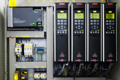
In this article, we will learn the working of an electrical AC drive.
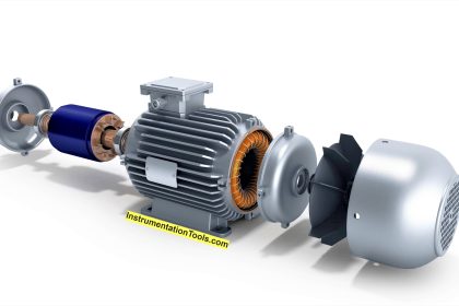
The AC drive has been around only since the 1970s. The growing popularity of AC drives is due to their ability to provide adjustable speed control with standard NEMA B design squirrel cage motors.
Other names for AC drives are variable frequency drive (VFD) and variable speed drive (VSD), but we’ll just call them AC drives.
AC drives are extremely popular due to energy savings, extended equipment life through reduced mechanical stress, elimination of excessive motor inrush current, and less wear and tear.
In this post, we will see the working of an AC drive.
How do AC Drives Work?
AC motor speed is controlled by frequency. An AC drive is a device for controlling the speed of an AC motor by controlling the frequency of the voltage supplied to the motor. It does this by first converting 3-phase 60 Hz AC power to dc power.
Then, by various switching mechanisms, it inverts this DC power into a pseudo sine wave3 phase adjustable frequency alternating current for the connected motor. Because of this, some people call AC drives “inverters,” although this is technically incorrect.
The frequency coming into the converter has a fixed frequency of 60 Hz. However, the adjustable frequency coming out of the inverter and going to the motor can be varied to suit the application.
There are two general types of solid-state frequency control systems available:
- Six-step and
- Pulse-width modulated (PWM) control
Let’s look at how an AC drive functions in a little more detail. The two main sections of a PWM drive are the converter and the inverter.
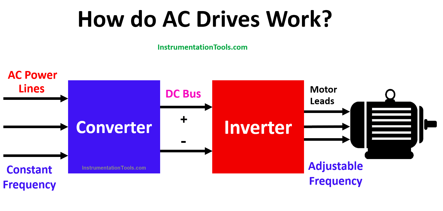
Three-phase 60 Hz AC power is coming into the converter.
The converter typically uses a rectifier (which is a solid-state device that changes AC to DC) to change the incoming 60 Hz AC into a rectified DC voltage.
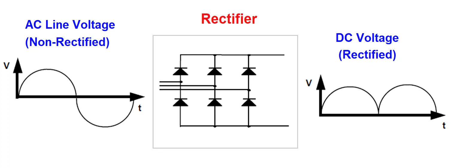
The DC voltage coming out of the converter is rather rough.
Different types of filtering can be used to smooth out the rectified DC so that it is of a more or less constant voltage value.
This filtering takes place between the converter and inverter stages. This “smoothed” DC is then sent on to the inverter.
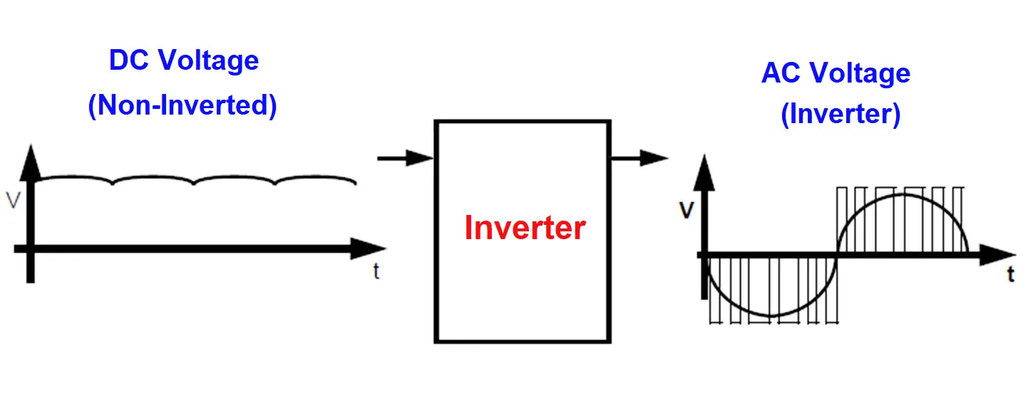
The inverter section produces an AC output which is fed to the motor. Positive and negative switching occurs within the Inverter which produces groups of voltage pulses.
The output frequency of a PWM drive is controlled by applying positive pulses in one-half cycle, and negative pulses in the next half cycle. The pulses within each group have varying widths that correspond to voltage values.
Notice on the output side of the inverter that the narrow voltage pulses represent the lower voltage values on the sine wave and that the wider voltage pulses represent higher voltage sine wave values.
The varying of pulse widths gives this method its name Pulse Width Modulation (PWM). This diagram is only showing 6 pulses per half cycle.
For each specific frequency, there is an optimum number of pulses and pulse widths that will closely simulate a pure sine wave.
Volts per Hertz Ratio
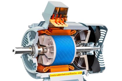
When current is applied to an induction motor it generates magnetic flux in its rotating field and torque is produced. This magnetic flux must remain constant in order to produce full-load torque.
This is most important when running a motor at less than full speed. And since AC drives are used to provide slower running speeds, there must be a means of maintaining a constant magnetic flux in the motor.
This method of magnetic flux control is called the volts-per-hertz ratio. With this method, the frequency and voltage must increase in the same proportion to maintain good torque production at the motor.
Electrical Drive Example
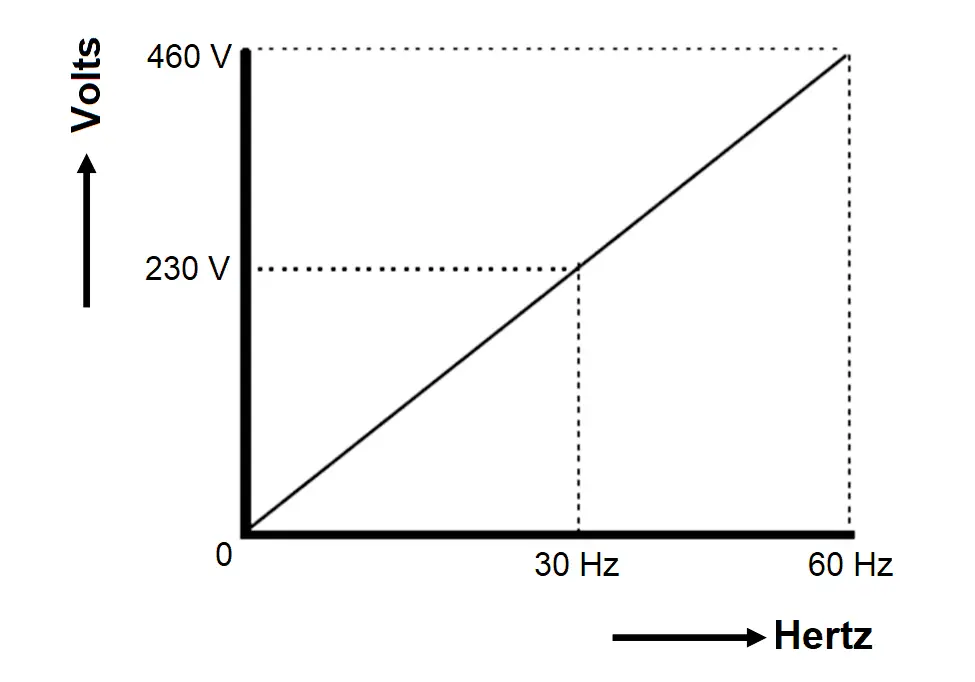
For example, if the frequency is 60 Hz and the voltage is 460 V, then the volts per Hertz ratio (460 divided by 60) would be 7.6 V/Hz.
So, at half speed on a 460 V supplied system, the frequency would be 30 Hertz and the voltage applied to the motor would be 230 V and the ratio would still be maintained at 7.6 V/Hz.
This ratio pattern saves energy going to the motor, but it is also very critical to performance.
The variable-frequency drive tries to maintain this ratio because if the ratio increases or decreases as motor speed changes, motor current can become unstable and torque can diminish.
On the other hand, excessive current could damage or destroy the motor.
PWM Drive
In a PWM drive, the voltage change required to maintain a constant Volts-per-Hertz ratio as the frequency is changed is controlled by increasing or decreasing the widths of the pulses created by the inverter.
And, a PWM drive can develop rated torque in the range of about 0.5 Hz and up. Multiple motors can be operated within the amperage rating of the drive (All motors will operate at the same frequency). This can be an advantage because all of the motors will change speed together and the control will be greater.
In this way, we understand how an AC drive works in general.
If you liked this article, then please subscribe to our YouTube Channel for Electrical, Electronics, Instrumentation, PLC, and SCADA video tutorials.
You can also follow us on Facebook and Twitter to receive daily updates.
Read Next:
- What is a Substation?
- Motor Cooling Methods
- Flame Retardant Cables
- SCADA in Power System
- Single and Multi-Core Cables


I would like to know more about ac drive, how to make setting and parameters