Inst ToolsInst ToolsInst Tools
  • Courses
  • Automation
    • PLC
    • Control System
    • Safety System
    • Communication
    • Fire & Gas System
  • Instrumentation
    • Design
    • Pressure
    • Temperature
    • Flow
    • Level
    • Vibration
    • Analyzer
    • Control Valve
    • Switch
    • Calibration
    • Erection & Commissioning
  • Interview
    • Instrumentation
    • Electrical
    • Electronics
    • Practical
  • Q&A
    • Instrumentation
    • Control System
    • Electrical
    • Electronics
    • Analog Electronics
    • Digital Electronics
    • Power Electronics
    • Microprocessor
  • Request
Search
  • Books
  • Software
  • Projects
  • Process
  • Tools
  • Basics
  • Formula
  • Power Plant
  • Root Cause Analysis
  • Electrical Basics
  • Animation
  • Standards
  • 4-20 mA Course
  • Siemens PLC Course
Reading: What is a Capacitor Bank?
Share
Font ResizerAa
Inst ToolsInst Tools
Font ResizerAa
  • Courses
  • Design
  • PLC
  • Interview
  • Control System
Search
  • Courses
  • Automation
    • PLC
    • Control System
    • Safety System
    • Communication
    • Fire & Gas System
  • Instrumentation
    • Design
    • Pressure
    • Temperature
    • Flow
    • Level
    • Vibration
    • Analyzer
    • Control Valve
    • Switch
    • Calibration
    • Erection & Commissioning
  • Interview
    • Instrumentation
    • Electrical
    • Electronics
    • Practical
  • Q&A
    • Instrumentation
    • Control System
    • Electrical
    • Electronics
    • Analog Electronics
    • Digital Electronics
    • Power Electronics
    • Microprocessor
  • Request
Follow US
All rights reserved. Reproduction in whole or in part without written permission is prohibited.
Inst Tools > Blog > Electrical Basics > What is a Capacitor Bank?

What is a Capacitor Bank?

Capacitor bank is used for reactive power compensation and power factor correction in the electrical substation.

Last updated: September 28, 2022 2:36 pm
R Jagan Mohan Rao
Electrical Basics
No Comments
Share
6 Min Read
SHARE

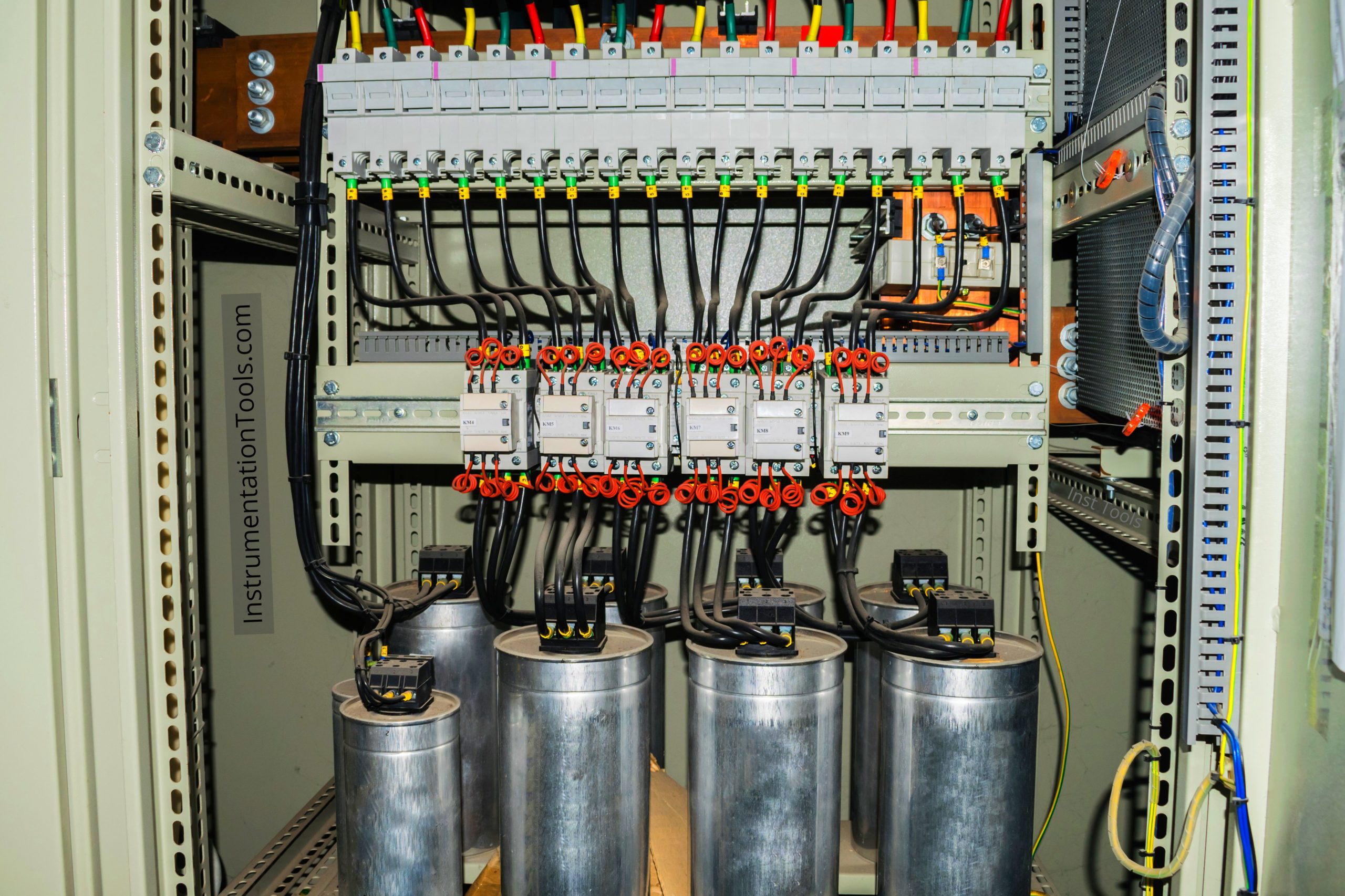
A capacitor bank is a physical group of several capacitors that are of the common specifications are connected in series or parallel with each other to form a capacitor bank that store electrical energy.

Contents
Capacitor BankTypes of Electrical LoadsActive or Real PowerReactive PowerApparent PowerPower FactorUses of a Capacitor Bank

The capacitor bank so formed is then used to correct a power factor lag or phase shift in an AC (alternative current) power supply.
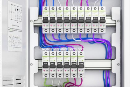
Capacitor Bank

Capacitor Bank

Let us go through some basics of electrical power system that makes us to know the importance of capacitor bank.

Types of Electrical Loads

In the electrical distribution system, loads are placed in one of three categories:

  • Resistive ( Incandescent light, heater)
  • Inductive ( Motor, A/C, Refrigerator)
  • Capacitive ( Capacitor)

Among the above three the most common of these on modern systems is the inductive load. General examples includes common lighting, transformer, AC induction motors, and furnaces etc., which draw not only active power from the supply but also reactive power (KVAR). 

A Common property of these inductive loads is that they utilize a winding to produce an electromagnetic field. Inductive field, which allows the motor to function and requires certain amount of electrical power in order to maintaining the field.

Active or Real Power

Active Power (KW) actually performs the work, it is the actual power measured in watts. It is product of Voltage, current, and Cos Ф.

Cos Ф is the angle between the voltage and current.

Power Factor Formula using Power Triangle figure

Reactive Power

Power required to establish magnetic fields around inductive components (lagging reactive power) and electric fields (leading reactive power) in capacitance components and then supply back into the supply system as these fields fall to zero.

The power which flows back and forth that means it moves in both the directions does not do any work in the circuit is called reactive power. Unit of measurement is VAR. product of Voltage, current, and sin Ф.

Almost all electrical devices are inductive in nature. Reactive Power (KVAR) sustains the electro-magnetic field.  Even though the reactive power is necessary for the equipment to operate correctly but could be understand as an undesirable burden on the supply.

Reactive power along with actual power which increases current in wire (real power current + reactive power current) also reduces power factor (pf).

Since electricity board charge only for active power the capacitor cannot generate or consume real power.

Since industries use inductive load it also uses huge amount of i2R losses in the wire resulting in more capacity grid and expenses for electricity board. Thus electricity boards not only measure active power but also measure reactive power.

Reactive power can be compensated by installing capacitor not one but many (usually bank which operates as per power factor being bad). The capacitor bank helps in increasing power factor (pf).
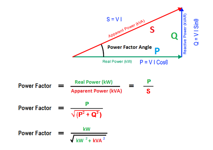
Apparent Power

The combination of above two power is called apparent power. The unit of measurement is VA. The apparent power is a product of voltage and current.

Power Factor

Basically, power is the capacity to do work. In electrical engineering, electrical power is the amount of electrical energy that can be transferred to some other form such as heat, light etc., per unit time.

The power factor is the ratio of actual power to the apparent power delivered to the load.

Power factor = Real or Actual power (KW)/Apparent power (kVA)

Uses of a Capacitor Bank

Since majority of the industrial loads are of inductive nature, they require certain proportion of reactive power for them to function.

This reactive power is provided by the capacitor bank installed parallel to the load.

Capacitor banks act as a source of local reactive power and thus less reactive power flow through the line.

By using a capacitor bank, the power factor can be maintained near to unity. Improving power factor is the process of reducing the phase difference between voltage and current.

Basically capacitor banks reduce the phase difference between the voltage and current.

On the addition of power bank, the current leads the voltage, hence the power factor angle is reduced. Reduction in power factor angle indicate the improvement of power factor.

Capacitor bank is used for reactive power compensation and power factor correction in the electrical substation.

If you liked this article, then please subscribe to our YouTube Channel for PLC and SCADA video tutorials.

You can also follow us on Facebook and Twitter to receive daily updates.

Read Next:

  • What is Electrical Busbar?
  • Torque Boosting in VFD
  • Types of Motor Enclosures
  • Electrical Single Line Diagram
  • What is an Instrument Transformer?
Don't Miss Our Updates
Be the first to get exclusive content straight to your email.
We promise not to spam you. You can unsubscribe at any time.
Invalid email address
You've successfully subscribed !

Continue Reading

What is a Time Delay Relay? Principle, Advantages, Disadvantages
Rotary Encoder Interview Questions and Answers
Difference Between MCB and RCBO
Difference Between Alternator and Generator?
Electrical Drives – Modes, Types, Speed Control Applications
Transformer Testing – Routine Tests of Transformers
Share This Article
Facebook Whatsapp Whatsapp LinkedIn Copy Link
Share
Leave a Comment

Leave a Reply Cancel reply

Your email address will not be published. Required fields are marked *

Stay Connected

128.3kFollowersLike
69.1kFollowersFollow
210kSubscribersSubscribe
38kFollowersFollow

Categories

Explore More

What is an Electrical Drive? Types, Advantages, Disadvantages
What is ELCB? Principle, Advantages, Disadvantages, Applications
Why Three-phase Voltage is 440 Volts?
Difference between Servo Motor and DC Motor
Difference Between AA and AAA Batteries
Difference Between MCB and MCCB
Electrical Drawings
Difference Between Earth and Neutral

Keep Learning

What is electrical transformer

Basics of Electrical Transformer

Why is HV Testing important in Electrical Panels?

Why is HV Testing important in Electrical Panels?

Things to Know When Measuring Voltage

Things to Know When Measuring Voltage

Automatic Transfer Switch

Automatic Transfer Switch (ATS) Using Classic Control Circuit

Induction Motor Operation

Induction Motor Over and Under Voltage Problems

What is a Magnetic Field

Difference Between Electric Field and Magnetic Field

Comparison of Electrical Protection Relays

Comparison of Electrical Protection Relays

Benefits of SIMOCODE over Intelligent MCC

Benefits of SIMOCODE over Intelligent MCC

Learn More

Tap Changing Switch Animation

Safety Instrumented System SIS Component Selection

SIS Component Selection – Safety Instrumented System

3-way globe valve

What is Mixing or Diverting Valve ?

Cathode Ray Tube (CRT)

Cathode Ray Tube (CRT)

PLC Sequential Operation Example Program

PLC Sequential Operation Example Program

Valve Positioner Torn apart

Pipeline Shakes Torn apart Valve Positioners

How to Calculate Network Speed?

Factors to Consider When Calculating Network Speed

Three Wire RTD Wheatstone bridge Circuit

RTD Wheatstone Bridge Circuits

Menu

  • About
  • Privacy Policy
  • Copyright

Quick Links

  • Learn PLC
  • Helping Hand
  • Part Time Job

YouTube Subscribe

Follow US
All rights reserved. Reproduction in whole or in part without written permission is prohibited.
Welcome Back!

Sign in to your account

Username or Email Address
Password

Lost your password?