Inst ToolsInst ToolsInst Tools
  • Courses
  • Automation
    • PLC
    • Control System
    • Safety System
    • Communication
    • Fire & Gas System
  • Instrumentation
    • Design
    • Pressure
    • Temperature
    • Flow
    • Level
    • Vibration
    • Analyzer
    • Control Valve
    • Switch
    • Calibration
    • Erection & Commissioning
  • Interview
    • Instrumentation
    • Electrical
    • Electronics
    • Practical
  • Q&A
    • Instrumentation
    • Control System
    • Electrical
    • Electronics
    • Analog Electronics
    • Digital Electronics
    • Power Electronics
    • Microprocessor
  • Request
Search
  • Books
  • Software
  • Projects
  • Process
  • Tools
  • Basics
  • Formula
  • Power Plant
  • Root Cause Analysis
  • Electrical Basics
  • Animation
  • Standards
  • 4-20 mA Course
  • Siemens PLC Course
Reading: Impedance in RC Circuits
Share
Font ResizerAa
Inst ToolsInst Tools
Font ResizerAa
  • Courses
  • Design
  • PLC
  • Interview
  • Control System
Search
  • Courses
  • Automation
    • PLC
    • Control System
    • Safety System
    • Communication
    • Fire & Gas System
  • Instrumentation
    • Design
    • Pressure
    • Temperature
    • Flow
    • Level
    • Vibration
    • Analyzer
    • Control Valve
    • Switch
    • Calibration
    • Erection & Commissioning
  • Interview
    • Instrumentation
    • Electrical
    • Electronics
    • Practical
  • Q&A
    • Instrumentation
    • Control System
    • Electrical
    • Electronics
    • Analog Electronics
    • Digital Electronics
    • Power Electronics
    • Microprocessor
  • Request
Follow US
All rights reserved. Reproduction in whole or in part without written permission is prohibited.
Inst Tools > Blog > Electrical Theory > Impedance in RC Circuits

Impedance in RC Circuits

Last updated: July 30, 2018 10:02 pm
Editorial Staff
Electrical Theory
No Comments
Share
1 Min Read
SHARE

In a capacitive circuit, as in an inductive circuit, impedance is the resultant of phasor addition of R and XC.

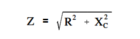
The below Equation is the mathematical representation for impedance in an R-C circuit.

Impedance in RC Circuits

Example:

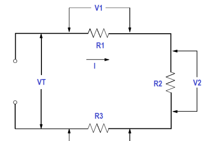
A 50 Ω XC and a 60 Ω resistance are in series across a 110V source (Figure 7). Calculate the impedance.

Simple RC Circuit

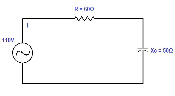
Figure 7 : Simple R-C Circuit

Solution:

Impedance in RC Circuits

Z = √ (602 + 502)

Z = √6100

Z = 78.1 Ω

Don't Miss Our Updates
Be the first to get exclusive content straight to your email.
We promise not to spam you. You can unsubscribe at any time.
Invalid email address
You've successfully subscribed !

Continue Reading

DC Circuit Analysis Loop Equations
Y and Delta Resistor Network Calculations
Induction Motor Torque Versus Slip
Series Circuit
DC Generator
Schematic Diagram
Share This Article
Facebook Whatsapp Whatsapp LinkedIn Copy Link
Share
Leave a Comment

Leave a Reply Cancel reply

Your email address will not be published. Required fields are marked *

Stay Connected

128.3kFollowersLike
69.1kFollowersFollow
210kSubscribersSubscribe
38kFollowersFollow

Categories

Explore More

Single Line Diagram
Shunt-Wound DC Generators
Capacitor
Batteries
Synchronous Motors
Single Phase Power Wiring Schemes
Starting of DC Motors
Calculate Power in Series RCL Circuit

Keep Learning

Left-hand Rule for Current Carrying Conductors

Magnetism

Parallel Circuit Unknown Resistance

Simplified Formulas for Parallel Circuit Resistance Calculations

Basic AC Generator

AC Generator Parts

Three Phase AC Generators

Three Phase AC Generators

Ground Detector Lamp Method Principle

Ground Detector Principle

Types of Batteries

Types of Batteries

DC Motor Connections

DC Motor Connections

DC Motor Action

DC Motor Speed

Learn More

PLC Programming for Weight-Based Packaging

PLC Programming for Weight-Based Packaging

Counters and Timers Projects Using Analog Electronic Devices

Top 100 Counters and Timers Projects Using Analog Electronic Devices

Why do we need to Control the Motion using VFD drives

Why do we need to Control the Motion using VFD drives?

pH Analyzers Questions and Answers

pH Meters Questions & Answers

Embedded Systems

Introduction to Embedded Systems – Features, Types, Applications

PLC Program for Trash Compactor

PLC Program for Trash Compactor

PLC Program for Positive edge pulse output for one scan cycle

PLC Program for Positive Edge Pulse Output for One Scan Cycle

PLC automation timers and counters

Medium-Level PLC Exercise for Students in Automation

Menu

  • About
  • Privacy Policy
  • Copyright

Quick Links

  • Learn PLC
  • Helping Hand
  • Part Time Job

YouTube Subscribe

Follow US
All rights reserved. Reproduction in whole or in part without written permission is prohibited.
Welcome Back!

Sign in to your account

Username or Email Address
Password

Lost your password?