A common type of semiconductor device used in electronics and power control applications is the Thyristor. It belongs to the family of silicon-controlled rectifiers (SCRs) and is designed to control the flow of electric current in a circuit. Thyristors are known for their ability to switch high currents and voltages with relatively low power input.
Thyristor
Thyristors are generally current-controlled electronic devices. It is a semiconductor device that may be activated by passing a gate current through the gate terminal (sometimes referred to as a gate triggering current)
Once it is turned on, it will keep conducting current until the forward current falls below a certain limit known as the holding current or until an external signal is supplied to turn it off, such as reverse voltage or a commutation circuit.
Although the transistor is a current-controlled device, it fails in two ways: once the base current of the transistor is removed, the device quickly shuts off, and it is unable to tolerate very high currents.
History of Thyristor
Thyristors have been around since the late 1950s. To increase the effectiveness of electronic power conversion, researchers were looking at several options. A group of scientists at Bell Laboratories, including William Shockley, started developing a semiconductor device that could regulate the flow of electricity.
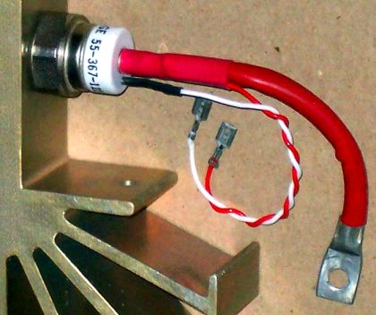
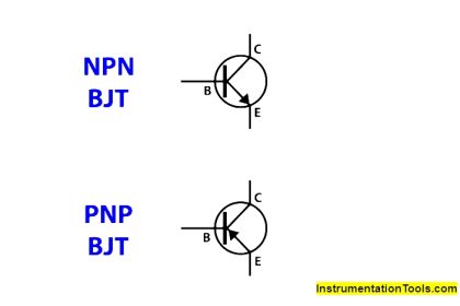
Fig 1. Basic Thyristor Type
As a result, the first thyristor-like structure, identified as the “PNPN” structure, was created in 1956. Gordon Hall and Frank W. “Bill” Jordan, two researchers at General Electric (GE), took the idea created at Bell Laboratories and improved it into a workable device known as the silicon-controlled rectifier (SCR) in 1957.
By employing a modest current to start a much greater flow of current, the four-layer semiconductor SCR may be used to regulate high-power electrical currents.
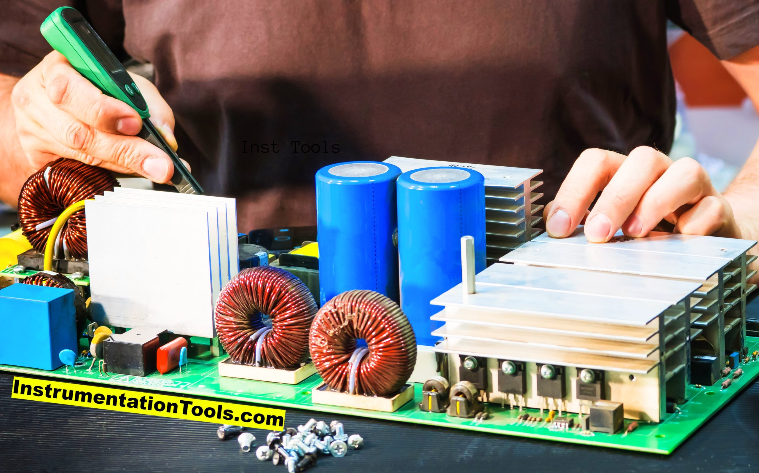
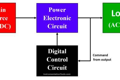
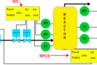
Fig 2. Applications of Power Electronics
Types of Thyristors
It’s important to note that thyristors are unidirectional devices, meaning they can only control current flow in one direction (from anode to cathode). For bidirectional current control, devices like TRIAC, which are essentially two thyristors connected in an inverse parallel configuration, are used.
There are several different types of thyristors, each with its own unique characteristics and applications. The most popular varieties are listed below:

Fig 3 . Different Types of Thyristors
Silicon-Controlled Rectifier (SCR)
The SCR is the most fundamental kind of thyristor, also referred to as a thyristor. It is a unidirectional device that has a controllable anode to cathode current flow.
SCRs are frequently utilized in applications including heating elements, power supply, motor control, and lighting.
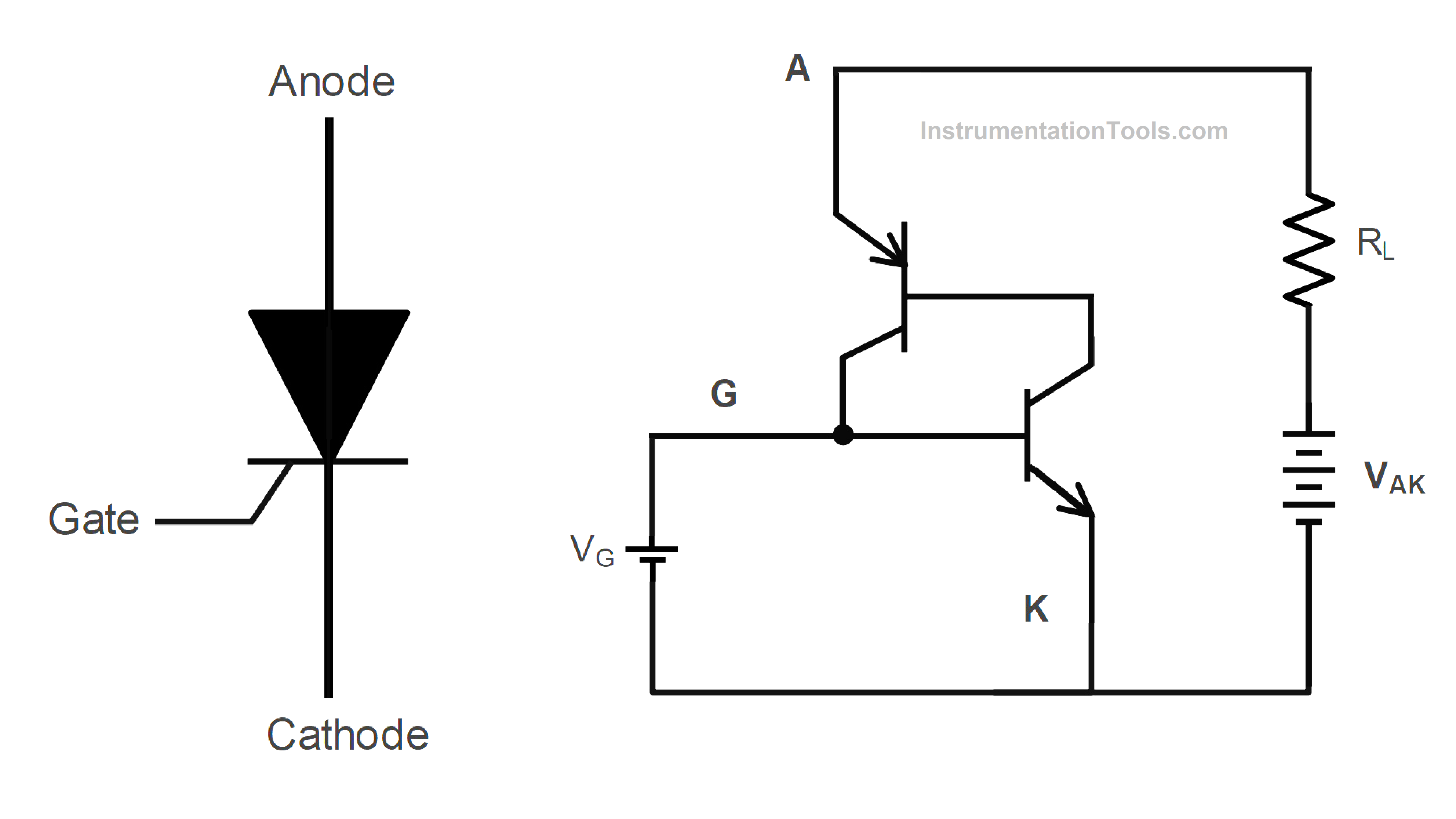
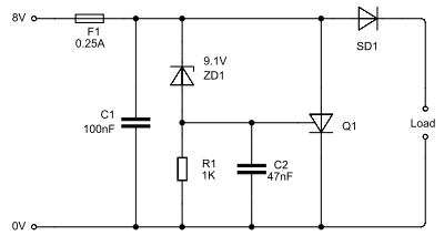
Fig 4. Silicon Controlled Rectifier
Reverse Conducting Thyristor (RCT)
RCTs provide both current conduction and current rectification by combining a thyristor and a diode in a single device. They are employed in situations like inductive load switching when both switching and rectification skills are necessary.
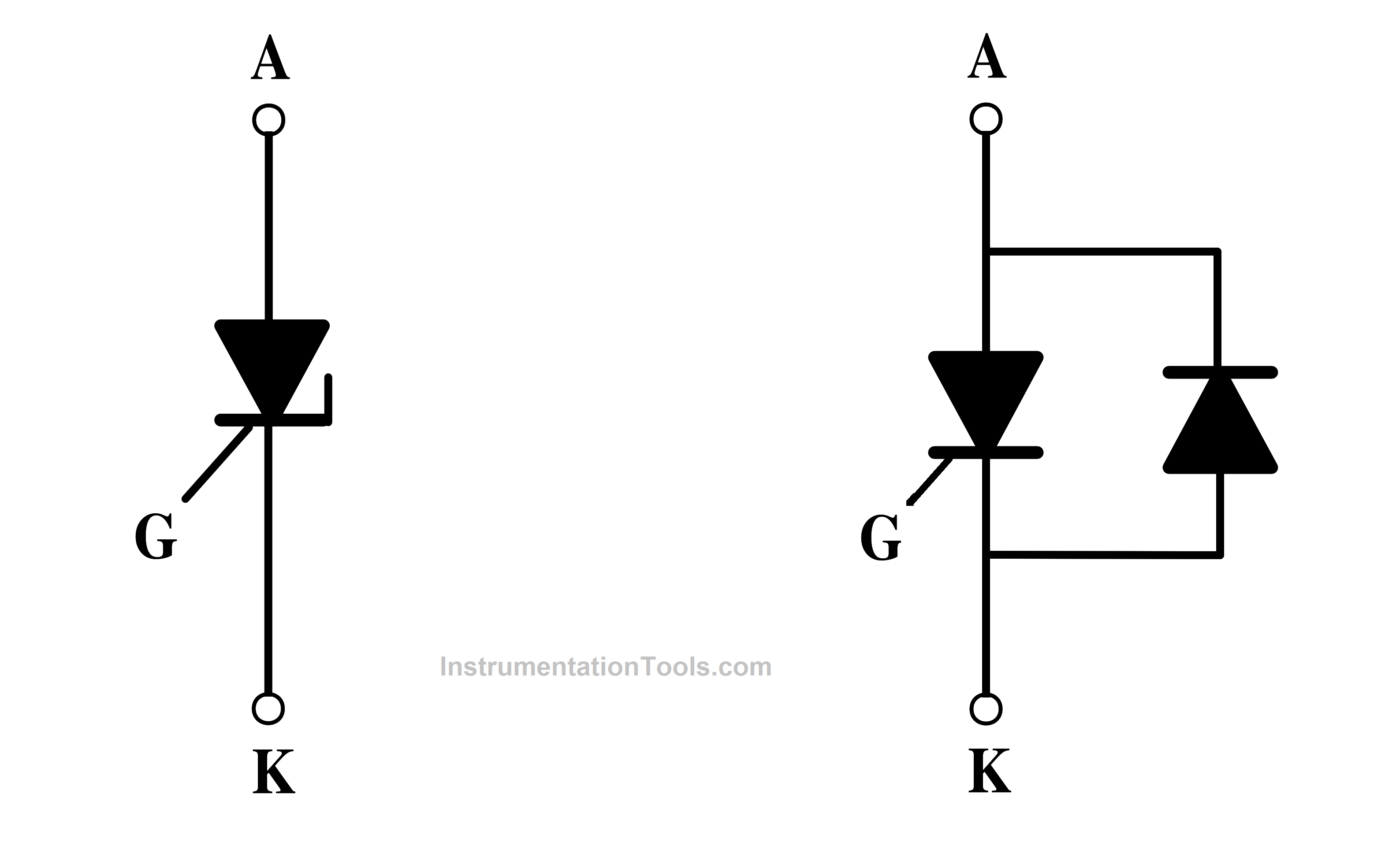
Fig 5. Reverse Conducting Thyristor Symbol and Equivalent Circuit
Fast Switching Thyristor
These thyristors were created for high-frequency switching applications that needed quick turn-on and turn-off periods. They are frequently found in pulse makers, switching power supplies, and high-frequency power converters.
FET-Controlled Thyristors (FET-CTH)
Applying enough voltage across the gate cathode, usually 3 V, turns it on. It produces the internal current that triggers the main thyristor. The driving requirements are lower than for an SCR since this device is voltage-controlled.
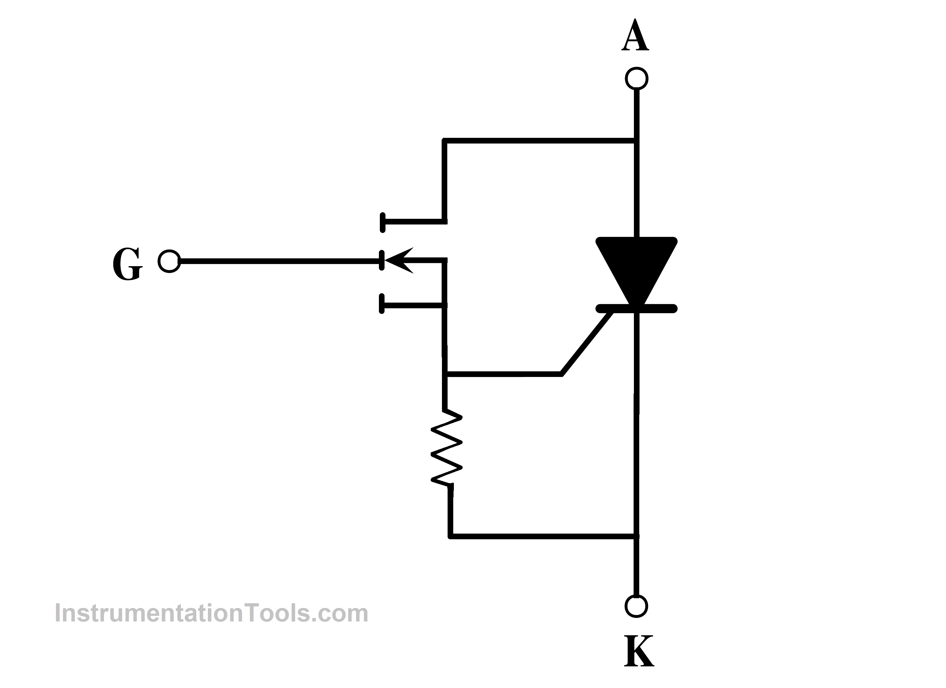
Fig 6. Equivalent Circuit of FET-controlled Thyristors
No gate control system can disable this thyristor. Its di/dt, dV/dt, and switching speed are all quite high. This gadget was unable to gain popularity due to the diversity of turn-off thyristors that were created over the course of two decades.
Static Induction Thyristor (SITH)
Static Induction Thyristor generally abbreviated as SITH is a self-controlled device similar to a gate turn-off thyristor. Field-controlled thyristor (FCT) and field-controlled diode (FCD) are further names for the SITH.
SITH has a gate mechanism that can stop the flow of anode current. It is a JFET structure with an extra injecting layer, a minority carrier device.
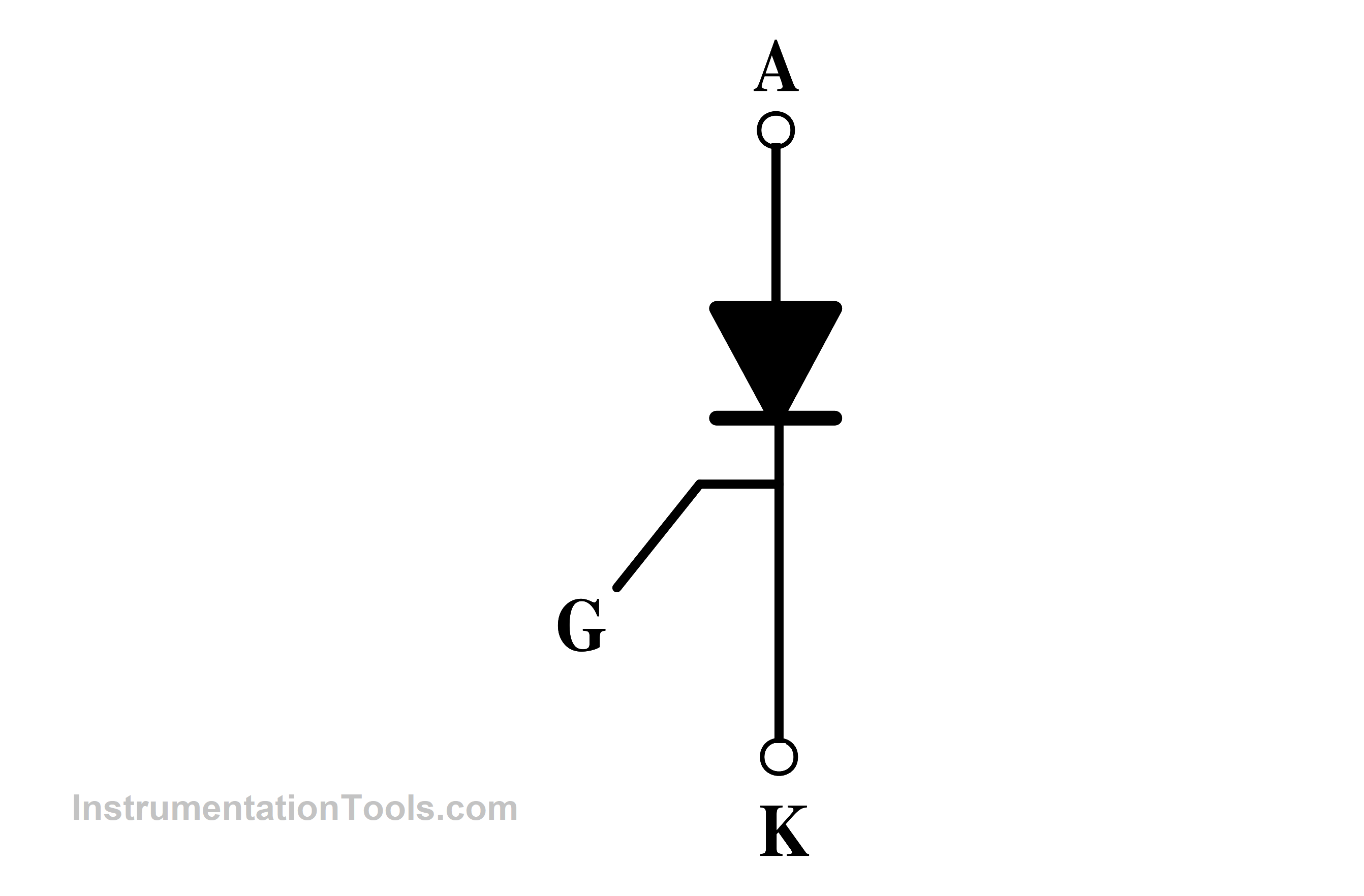
Fig 7. Static Induction Thyristor
SITH has a low on-state resistance and thus a low voltage drop since it is a minority carrier device. A pin diode with a gate structure that can choke off anode current flow, that is essentially what the device is.
Due to the possibility of increased current densities and hence bigger cathode areas, large-area devices are often buried-gate types. The maximum low current rating for SITH devices is 500 A, whereas the maximum high voltage rating is 2.5 kV.
Gate Commutated Thyristor (GCT)
GCTs are specialized thyristors that actively switch off the device using external circuitry. They are therefore appropriate for high-voltage and high-current applications where a quick turn-off is necessary.
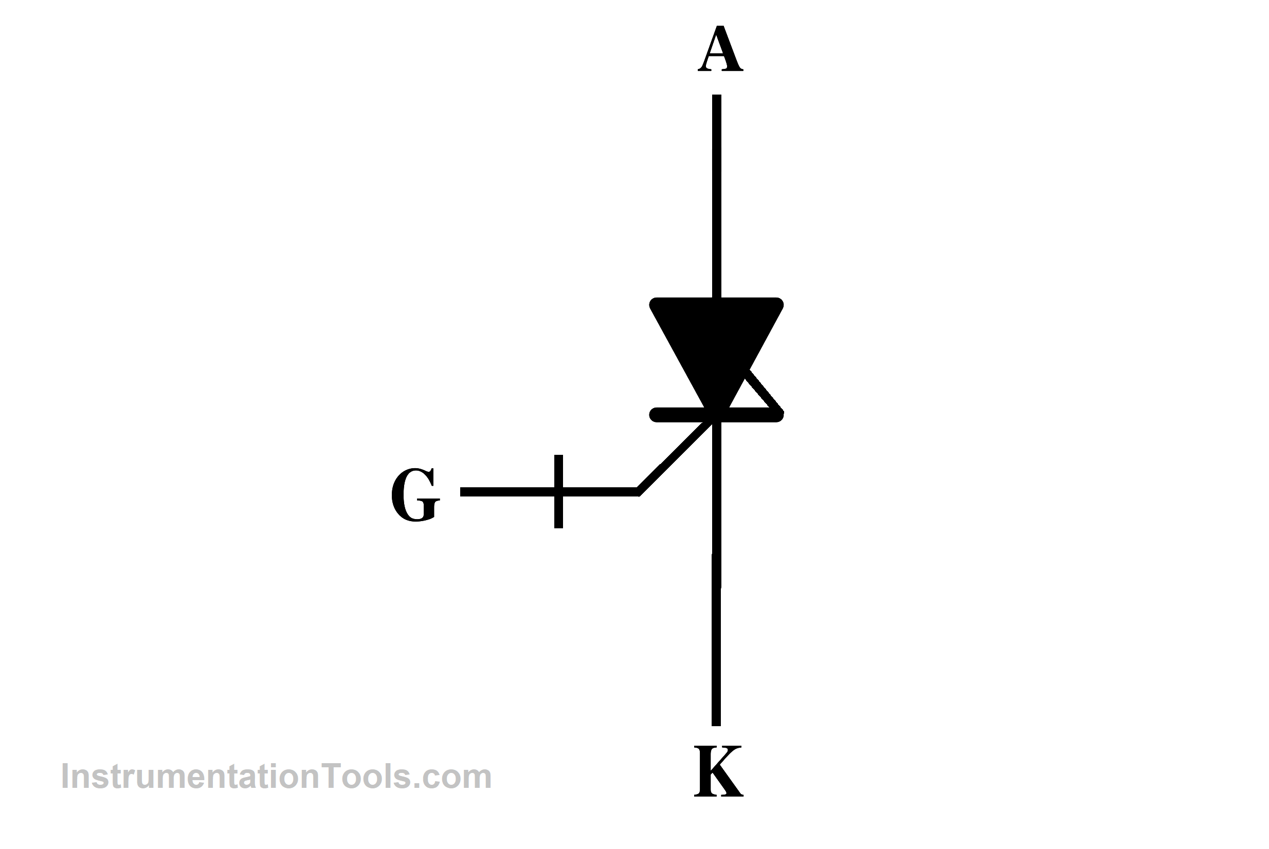
Fig 8. Gate Commutated Thyristor Symbol
Integrated Gate-Commutated Thyristor (IGCT)
GTO and GCT properties are combined in IGCTs, which also include built-in gate-commutation circuitry and improved switching capabilities. They are employed in high-power applications such as high-voltage direct current (HVDC) systems, renewable energy systems, and industrial motors.
Emitter Turn OFF Thyristor (ETO)
One form of thyristor that may be turned ON and OFF using a MOSFET is the Emitter turn OFF thyristor. It has the benefits of both the MOSFET and the GTO. It comprises two gates- one gate is used to turn ON and another gate with a series MOSFET is used to turn OFF.
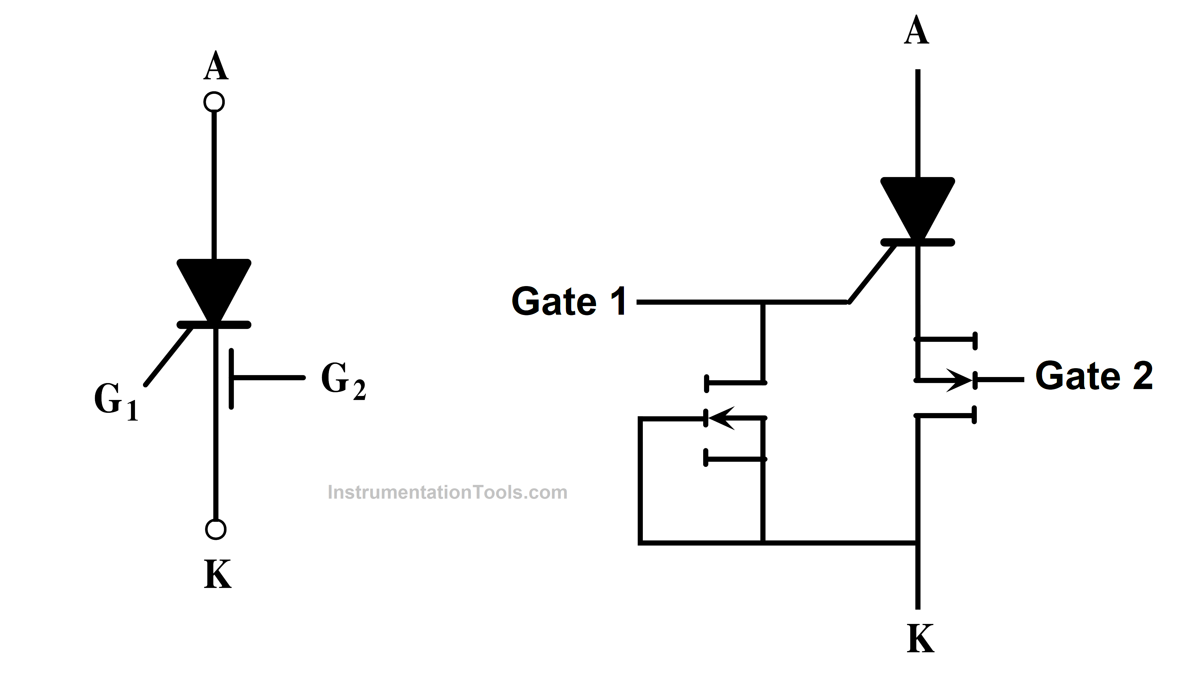
Fig 9. Emitter Turn Off Thyristor
MOS turn-off thyristor (MTO)
MOS turn-off thyristor is referred to as MTO. Both the MOSFET and the Gate Turn-off Thyristor (GTO) are components of this high-power bipolar MOS thyristor. It was created to take the position of GTO.
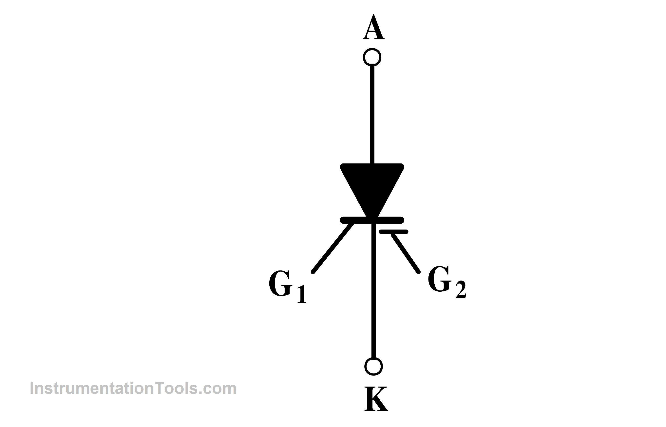
Fig 10. MOS Turn-off Thyristor Symbol
It is a latching device that works better in terms of power and blocking voltages than MCT and IGBT. It was created by Silicon Power Company (SPCO), and functions similarly to the GTO, but it also has a reduced pulse current OFF state.
Gate Turn-Off Thyristor (GTO)
GTO thyristors can be turned on by a gate signal as well as turned off by a negative gate signal. This makes them more versatile than standard SCRs, which can only be turned off by reducing the anode current. GTOs find use in applications like high-power motor drives, inverters, and industrial equipment.
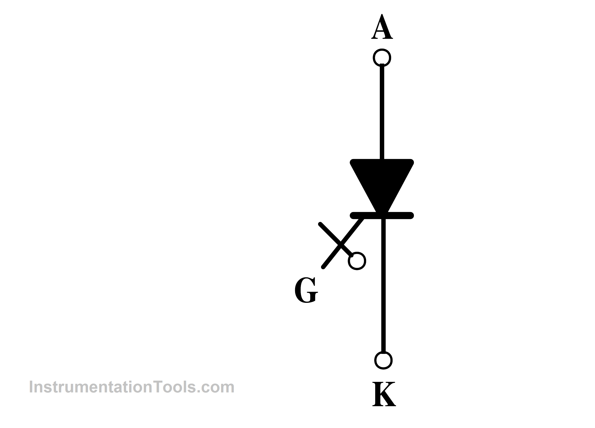
Fig 11. Gate Turn-off Thyristor Symbol
TRIAC
Triacs are bidirectional devices made up of two parallel, but inverted-polarity, SCR-like structures. Bidirectional control is the ability to control current flow in both directions. Triacs are frequently employed in applications including AC power management, fan speed regulation, and light dimming.
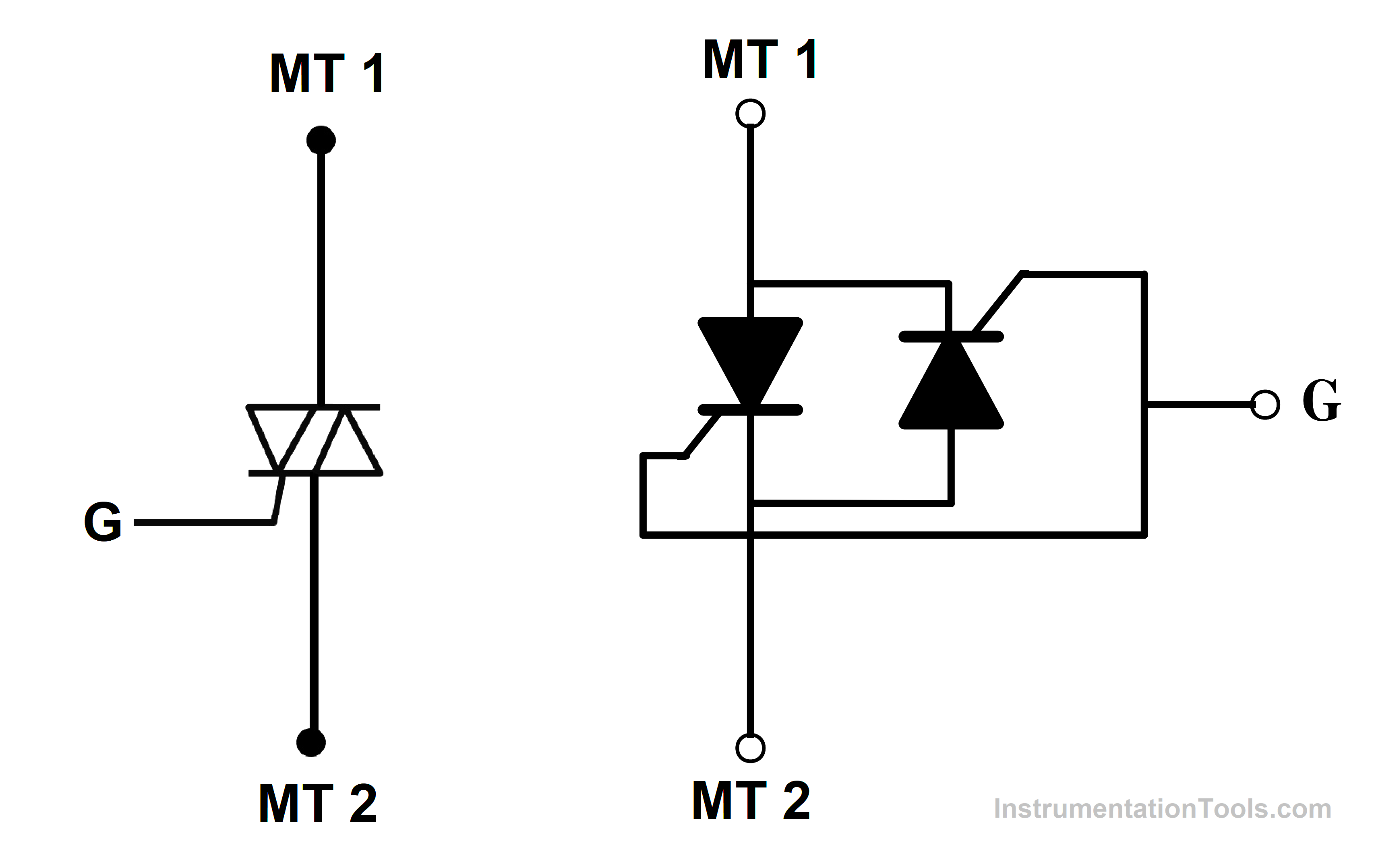
Fig 12. TRIAC symbol and equivalent circuit
DIAC
The diac is a trigger that starts the conduction process in a triac. When a specific voltage threshold is met, the gadget, which is bidirectional, conducts. To build straightforward AC switching circuits, diacs, and triacs are frequently combined.
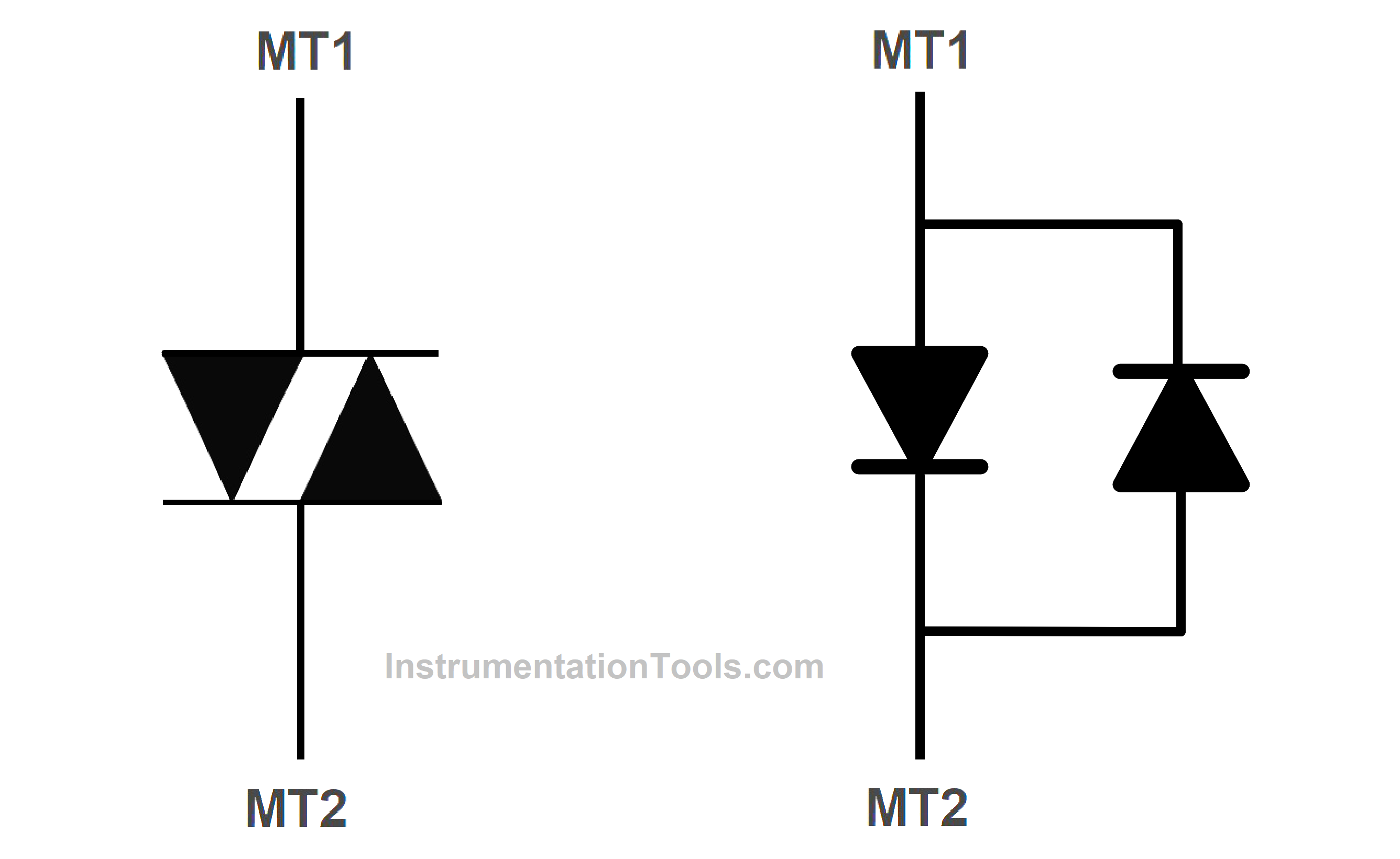
Fig 13. DIAC symbol and equivalent circuit
Bidirectional Phase-Controlled Thyristor (BCT)
BCT uses two thyristors ( SCR ) in an anti-parallel configuration in a single device. It has two separate gate terminals one for each thyristor. One of the gate terminals turns on the current in the forward direction and the other gate terminal turns on the current in the reverse direction.
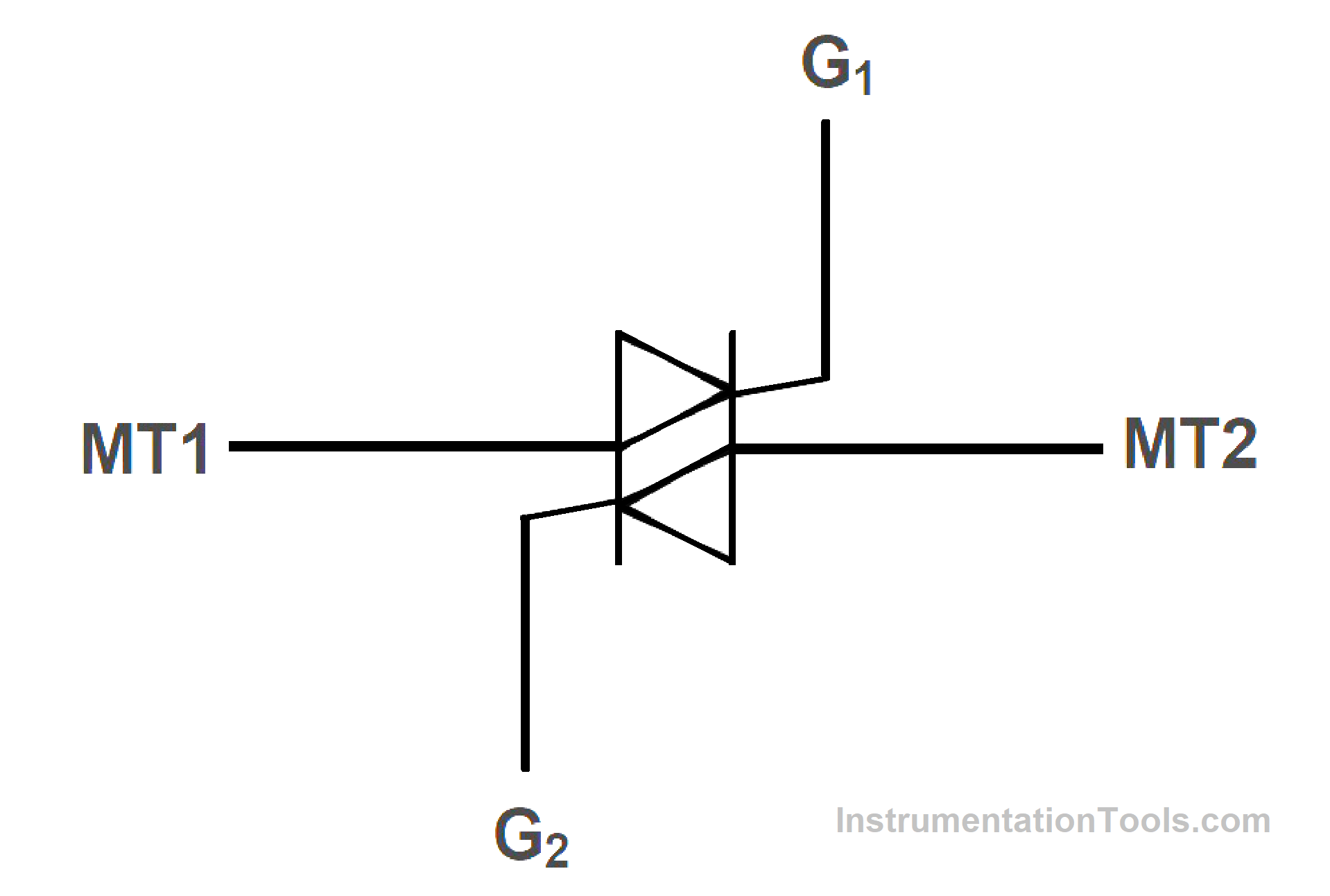
Fig 14. Bidirectional Phase-controlled Thyristor Symbol
Thyristor Applications
Thyristors have been used in a wide range of applications like UPS, high-voltage direct current (HVDC) transmission systems, and more including electric motor drives, voltage regulation, lighting control, and uninterruptible power supply.
Reference
- “Power Electronics: Circuits, Devices and Applications“, M H Rashid, Pearson Education
- “ Power Electronics” P. S. Bimbhra, Khanna Publishers, 2012
If you liked this article, then please subscribe to our YouTube Channel for Instrumentation, Electrical, PLC, and SCADA video tutorials.
You can also follow us on Facebook and Twitter to receive daily updates.
Read Next:
- What is Power Electronics?
- Turning OFF SCR Commutation
- Types of Power Electronic Devices
- Power Diode Working Principle
- IGBT Characteristics & Advantages