A well-written PLC program code is a very important aspect of your programming because it helps you troubleshoot any faults in your process fast and easily. Also, it will help engineers to understand your PLC logic by following these best practices and tips..
In this article, you’ll find some tips and remarks that you need to take into consideration before and while writing a PLC code.
To ensure a clean, well-written, and easy-to-read PLC code.
PLC Programming Best Practices and Tips

The below-mentioned PLC tips and tricks will be discussed here.
- Don’t abuse the SET/RESET instructions.
- IOs segregation.
- Programming analog IOs.
- Wait for your inputs to smooth out.
- Alarms and Notifications.
- Set points.
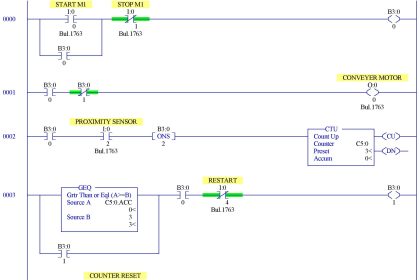
Don’t Abuse the SET/RESET Instructions
You shouldn’t abuse (overuse) the SET and RESET instructions in your code.
- You want to energize a BIT in only one place in your code, to make it easier to troubleshoot your program. If in case that bit didn’t work or worked when it shouldn’t.
- So using SET and RESET to energize the same bit in many different locations in your PLC code will make it hard to debug if there is something wrong with your code.
- That doesn’t mean that you shouldn’t use SET and RESET commands, just means that you should be careful not to set and reset the same bit in many places.
And if you have to, you can use branches to set and reset the same bit in the same Rung, regardless of how many branches activates this bit, to make it easier to follow that bit when in need.
IO Segregation
Programming Digital Inputs:
When setting your digital inputs in your PLC program, it is better to not use them directly in your code. Instead, you should use this input bit to trigger another memory bit (a marker or a tag in the PLC) and then use this new tag as a representation of this input, throughout the whole PLC program.
i.e., input %I0.0 (start input) will trigger a bit %M0.0 in the PLC and this bit will be used as a representation of the start input throughout the PLC code.
Why are we using a bit instead of just directly looking at the input itself ??
It is a best practice to do it this way, in case of whatever reason that led us to change that input from %I0.0 to %I0.4 we don’t want to hunt down the input %I0.0 in the whole program and change it to %I0.4 cause that might take a long time if you are using this input in many locations in your code, and also you might slip and miss some input unchanged, which will mess up your PLC program.
So instead of that, we just change it in one line and the change will be directly implemented to all % M0.0 that I am using in my program.
This technique is known as Segregation.
Same goes for outputs:
I will use a PLC memory bit to energize the output bit and use this memory bit throughout the whole program.
Programming Analog IOs
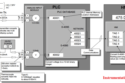
When dealing with analog inputs, we have to prepare our signal first before dealing with it in our PLC code. Because analog signals will come to the PLC as either a 0-10V or 4-20mA depending on sensor type, and this range of value will refer to the actual physical quantity that the sensor is measuring, whether its Temperature, pressure, level, …etc.
This is called signal scaling, which is converting the analog signal from the volts or amperes range to the actual value that the sensor is measuring.
There are preprogrammed blocks inside the PLC that execute scaling for you, such as SCALE and Normalize blocks in TIA Portal or SCP Block in Allen Bradley.
As a best practice when dealing with analog signals, it is best to set the upper and lower ranges to your scaled value to avoid having a value that is negative or a value that is bigger than what the sensor can detect.
For example: if you have a sensor that is giving you a 4-20mA in correspondence to a 0-100% level, in any case, that the input will be less than 4 or greater than 20, you don’t want your scaling to give you a negative level or a level value higher than 100%.
So we compare the input to a minimum and maximum values (4-20mA) and force the scaling to give us logical values in such cases.
Another good practice is to set an alarm if the input value exceeded its limits for a certain period of time. To warn the operator that the sensor might be defective or there may be some problem in the field.
Waiting for Inputs to Smooth Out
When you are waiting for an input signal that is coming from a sensor that measures a physical quantity like temperature, pressure, or fluid level whether it’s an analog or digital signal. You want to wait for your signal until you make sure that this isn’t just a noise in your system and that you actually reached this certain level.
Imagine a water tank where you are waiting for a high-level sensor to be activated to stop the filling pump, you should expect that when the water is around the high level, the sensor will jump back and forth between on and off or will jump around that level value (if it is an analog sensor), so we need to wait for our signal to smooth out, to avoid running and stopping the pump several times in a short period to protect it from burning out.
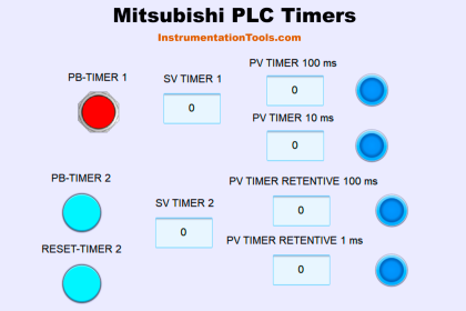
So, as a best practice tip, you should always use a timer with that input signal and only start to take actions when the signal is stable for a certain amount of time ( 10 sec for example).
Alarms and Notifications
Alarms and notifications are used to tell us that the system/process has some problems, something is not right, or something needs your attention.
An alarm will almost always stop your process or part of it until the cause of the alarm doesn’t exist anymore. For example, an overheating alarm of an oven will stop all heating zones, until this condition is cleared.
A notification will just tell you that something is out of the ordinary, but not necessarily enough to stop the process, like a water tank level is slightly increased above limits.
As a best practice, you need to always use a dual-bit alarm/notification coding, to separate between them, so you can give the operator the choice to silence the notification siren or flasher without waiting for the alarm condition to be cleared.
You will have two separate bits, one for the alarm which will stop the process and will only be reset when the alarm condition is cleared. Another bit will be for activating a flasher or a siren to inform the operator that something is wrong with the process.
Considerations
- Safety for operators and process.
- Operation necessity.
- The alarm self-reset or the operator must reset.
- Should I use a delay timer ( water level alarm ) or immediately set the alarm (Emergency Stop or a Circuit Breaker trip)
- After you set up your alarms, don’t forget to incorporate these alarms in your logic control, for example when the high-level alarm is active, the feeding pump shouldn’t work, so you should add this condition to your pump coding.
Set points
Another good practice when coding your program is to keep in mind that every constant value that you use is bound to be changed at some time, so you might as well make it configurable from the beginning.
For example, if you’re using a timer and you set the preset time to 10 sec. if in the future the operator wanted to change it to 5 or 15 sec, it will be very comfortable for everyone’s sake to have this set point configurable from the coding step.
Every constant value can be set up as configurable values, you just need to ask yourself what will make the operator experience easier and more efficient and what isn’t necessary.
Conclusion
The above-mentioned tips will optimize your PLC programming and coding skills, make it clean and easy to read and make working with the system easier for you and everyone else.
If you liked this article, then please subscribe to our YouTube Channel for Electrical, Electronics, Instrumentation, PLC, and SCADA video tutorials.
You can also follow us on Facebook and Twitter to receive daily updates.
Read Next:
- Motor Feedback PLC Logic
- Steps in PLC System Design
- SCADA System Vulnerabilities
- Delta PLC and VFD with Modbus
- Industrial Automation Documents