This is a PLC Program to detect burned chips and remove them by using PLC. Learn PLC programming with food industry examples.
Food Processing Industry
Problem Description
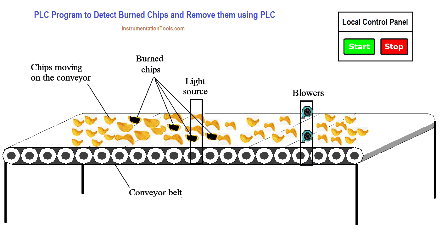
Potato chips are made in the company and sent to final packing. As per the process we need to identify the chips because in chips some chips might be burned.
Burned chips should be removed from the conveyor. Make a PLC program for the application which can detect burned chips and remove them.
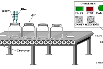
Problem Diagram
PLC Solution
To detect burned chips light sensor are used. Light dependent resistors (LDR) are used to detect the burned chips.
Blowers are used to throw away the burned chips from the conveyor whenever burned chips detected.
Blowers are used to throw away burned chips from the conveyor. Here we used two blowers, number of blowers depend on the size of the conveyor.
Time measurement is necessary for blower cycle. Here we measure time taken by chips to reach from light source to blower.
Note:- Here we consider simple application for detecting burned chips on the conveyor and remove them. We have taken here light source to detect burned chips on the bases of darkness of the chips.
List of inputs and outputs
Digital Inputs
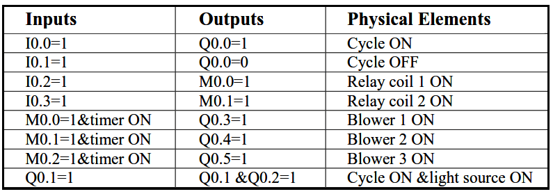
- START PB :- I0.0
- STOP PB :- I0.1
- LDR 1:- I0.2
- LDR 2 :- I0.3
Digital Outputs
- Cycle ON :- Q0.0
- Conveyor :- Q0.1
- Light source :- Q0.2
- Blower 1 :- Q0.3
- Blower 2 :- Q0.4
M memory
- Relay coil 1 : M0.0
- Relay coil 2: M0.1
PLC Program for detecting burned chips and removing them


PLC Program Explanation
For this application, we use S7-300 PLC and TIA portal software for programming. We can implement this logic by using other PLC also.
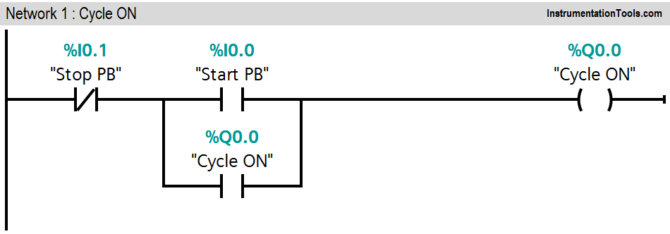
Network 1:
In first network we used latching circuit for cycle ON. Here we used START PB (I0.0 ) to start the cycle and STOP PB (I0.1) to stop the cycle.
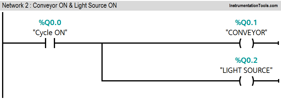
Network 2:
When cycle is ON (Q0.0), Conveyor (Q0.1) and light source (Q0.2) will be ON.
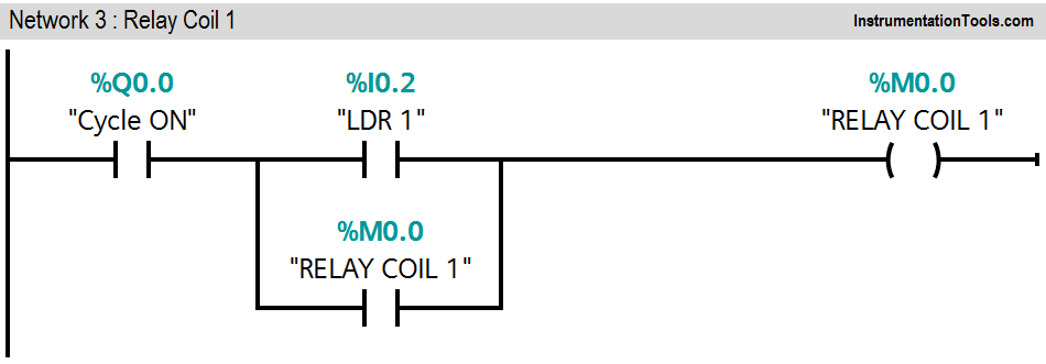
Network 3:
Cycle is ON and LDR 1 (I0.2) is detected, Relay coil 1(M0.0) will be ON
Network 4:
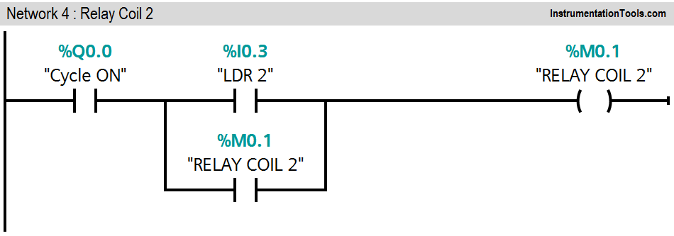
Cycle is ON and LDR 2 (I0.3) is detected, Relay coil 2 (M0.1) will be ON
Network 5:
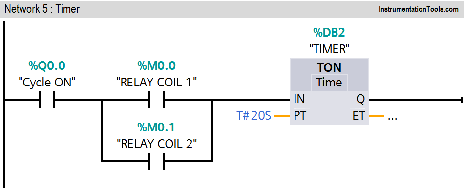
Either relay coil 1 (M0.0) or relay coil 2 (M0.1) is ON, Timer instruction will be executed. During this operation cycle is ON.
Network 6:
When cycle is ON (Q0.0) and timer output is ON, blower 1 will be ON.
Network 7:
When cycle is ON (Q0.0) and timer output is ON, blower 2 will be ON.
When LDR sensors detect burned chips on the conveyor, blower’s timer (20s) will be ON and it will throw away the burned chips from the conveyor. Here we assumed 20s travelling time taken by chips to reach from light source to blowers.
Number of blowers is depended on the size of the conveyor.
Note:- Above application may be different from actual application. This example is only for explanation purpose only. We can implement this logic in other PLC also. This is the simple concept of detecting burned chips on the conveyor and remove them by PLC logic. All parameters considered in example are for explanation purpose only, parameters may be different in actual applications.
Result
If you liked this article, then please subscribe to our YouTube Channel for PLC and SCADA video tutorials.
You can also follow us on Facebook and Twitter to receive daily updates.
Read Next:
- PLC Reads from Field Transmitters
- Troubleshoot a PLC System
- PLC Architecture
- Difference between PLC & DCS
- Automation Engineers Questions





Much needed explaination Sir. Thank you so much