Inst ToolsInst ToolsInst Tools
  • Courses
  • Automation
    • PLC
    • Control System
    • Safety System
    • Communication
    • Fire & Gas System
  • Instrumentation
    • Design
    • Pressure
    • Temperature
    • Flow
    • Level
    • Vibration
    • Analyzer
    • Control Valve
    • Switch
    • Calibration
    • Erection & Commissioning
  • Interview
    • Instrumentation
    • Electrical
    • Electronics
    • Practical
  • Q&A
    • Instrumentation
    • Control System
    • Electrical
    • Electronics
    • Analog Electronics
    • Digital Electronics
    • Power Electronics
    • Microprocessor
  • Request
Search
  • Books
  • Software
  • Projects
  • Process
  • Tools
  • Basics
  • Formula
  • Power Plant
  • Root Cause Analysis
  • Electrical Basics
  • Animation
  • Standards
  • 4-20 mA Course
  • Siemens PLC Course
Reading: Ultrasonic Tank Gauging
Share
Notification Show More
Font ResizerAa
Inst ToolsInst Tools
Font ResizerAa
  • Courses
  • Design
  • PLC
  • Interview
  • Control System
Search
  • Courses
  • Automation
    • PLC
    • Control System
    • Safety System
    • Communication
    • Fire & Gas System
  • Instrumentation
    • Design
    • Pressure
    • Temperature
    • Flow
    • Level
    • Vibration
    • Analyzer
    • Control Valve
    • Switch
    • Calibration
    • Erection & Commissioning
  • Interview
    • Instrumentation
    • Electrical
    • Electronics
    • Practical
  • Q&A
    • Instrumentation
    • Control System
    • Electrical
    • Electronics
    • Analog Electronics
    • Digital Electronics
    • Power Electronics
    • Microprocessor
  • Request
Follow US
All rights reserved. Reproduction in whole or in part without written permission is prohibited.
Inst Tools > Blog > Level Measurement > Ultrasonic Tank Gauging

Ultrasonic Tank Gauging

Last updated: January 26, 2020 5:29 pm
Editorial Staff
Level Measurement
No Comments
Share
3 Min Read
SHARE

Ultrasonic Tank Gauging is a non-contacting level measurement method. The sensors emit acoustic frequency waves in the range of 20 kHz to 200 kHz that is reflected back from the liquid surface and detected by the emitting transducer.

Ultrasonic level sensors can be affected (due to the change of speed of sound) by factors such as moisture, temperature, and pressures. To overcome this, correction factors are applied to the level measurement to improve measurement accuracy.

Ultrasonic Tank Gauging

Ultrasonic Tank Gauging

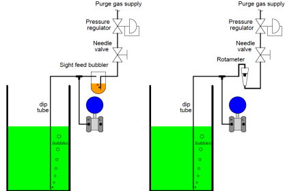
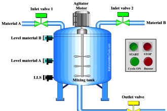
Figure: Simple diagram to demonstrate an ultrasonic level measurement system

Mounting and positioning of the ultrasonic transducer is key to ensuring the best response to reflected transmissions. Additionally, the tank should be relatively free of obstacles such as brackets or ladders so that false returns are minimized.

A widely recorded shortcoming of ultrasonic tank gauging systems is that they are susceptible to ringing. This occurs when the transmitted signal is reflected back to the transducer from an unintended surface, namely a surface other than that of the liquid in the tank. Ringing can be compensated for and, in a lot of cases, minimized so that it has a negligible impact on measurement accuracy.

An additional shortcoming is that it has been widely accepted throughout the industry that non-contacting ultrasonic devices are erroneous when used in vacuumed nitrogen blanketed storage tanks. Accuracy can be improved by having a fixed reference point within the tank and to instead continuously monitor the changes in level with respect to this fixed point .

This tank level measurement system is relatively cheap when compared to alternative systems that offer comparable accuracy.

This method of level measurement is widely viewed as being inaccurate; this is caused by the effect that gasoline vapor has upon the measurement. Both system manufacturers and system solution designers and installers have stated that this technology should not be used on gasoline or any fuel storage tanks.

References: Lewis WA (1994) Confusion Over Tank Gauging. Control and Instrumentation 1994, volume 26, Issue 9, pp11

Read Next:

  • Ultrasonic Level Measurement
  • Purpose of Tank Gauging
  • Level Measurement Terminology
  • Wire Guided Float Detectors
  • Level Detection Switches
Don't Miss Our Updates
Be the first to get exclusive content straight to your email.
We promise not to spam you. You can unsubscribe at any time.
Invalid email address
You've successfully subscribed !

Continue Reading

Micro-impulse Level Transmitter Principle
Inductively Coupled Wire Guided Float Detectors
Radar Level Transmitter in Briddle level Measurement
Purpose of Tank Gauging Level Measurement
Advantages & Disadvantages of Level Measurement Systems
Conductive Level Switch Principle
Share This Article
Facebook Whatsapp Whatsapp LinkedIn Copy Link
Share
Leave a Comment

Leave a Reply Cancel reply

Your email address will not be published. Required fields are marked *

Stay Connected

128.3kFollowersLike
69.1kFollowersFollow
210kSubscribersSubscribe
38kFollowersFollow

Categories

Explore More

Pressure Transmitters Leg Compensation Technique
Level Instruments Design Rules
Magnetic Level Gauge Working Principle Animation
Conductive Level Measurement Working Principle
Drum Level Compensation and Range Calculation of DP Transmitter
what is a Bubbler System?
Hydrostatic Level Measurement
DP Level Transmitters Compensation Techniques

Keep Learning

Level-Transmitters-Animation

Level Transmitter Animation

Practical Level Sensors Questions and Answers

Practical Level Sensors Questions and Answers

Why Measure Level

Zero Interface Level Calculation

How to do Interface Level Calculation using DP Transmitter ?

Types of Tank Gauging Level Measurement Systems

Types of Tank Gauging Level Measurement Systems

Ultrasonic level measurement

Ultrasonic Level Measurement

Differential Pressure Level Transmitter Errors

Differential Pressure Level Transmitter Errors

Hydrostatic pressure Measurement

Basics of Hydrostatic Level Measurement

Learn More

How to Check the Continuity of Protective Conductors

How to Check the Continuity of Protective Conductors?

Inductive proximity switches

How to Connect Proximity Switch (Sink Type) to Make LED ON ?

Liquid Level Switch Control Pump and Lamp

Liquid Level Switch Control Pump and Lamp

PLC Program for Positive edge pulse output for one scan cycle

PLC Program for Positive Edge Pulse Output for One Scan Cycle

Phase angle

AC Generation Analysis : Effective Values, Phase Angle and Frequency

Mechanical Torsion Meter Principle

Mechanical Torsion Meter Principle

Parts of Safety PLC

SIS Software Simulation – Safety Instrumented System

Area Velocity Flow Meter Principle

Area Velocity Flow Meter Principle

Menu

  • About
  • Privacy Policy
  • Copyright

Quick Links

  • Learn PLC
  • Helping Hand
  • Part Time Job

YouTube Subscribe

Follow US
All rights reserved. Reproduction in whole or in part without written permission is prohibited.
Welcome Back!

Sign in to your account

Username or Email Address
Password

Lost your password?