Inst ToolsInst ToolsInst Tools
  • Courses
  • Automation
    • PLC
    • Control System
    • Safety System
    • Communication
    • Fire & Gas System
  • Instrumentation
    • Design
    • Pressure
    • Temperature
    • Flow
    • Level
    • Vibration
    • Analyzer
    • Control Valve
    • Switch
    • Calibration
    • Erection & Commissioning
  • Interview
    • Instrumentation
    • Electrical
    • Electronics
    • Practical
  • Q&A
    • Instrumentation
    • Control System
    • Electrical
    • Electronics
    • Analog Electronics
    • Digital Electronics
    • Power Electronics
    • Microprocessor
  • Request
Search
  • Books
  • Software
  • Projects
  • Process
  • Tools
  • Basics
  • Formula
  • Power Plant
  • Root Cause Analysis
  • Electrical Basics
  • Animation
  • Standards
  • 4-20 mA Course
  • Siemens PLC Course
Reading: PLC Analog Input Sampling Ladder Logic
Share
Notification Show More
Font ResizerAa
Inst ToolsInst Tools
Font ResizerAa
  • Courses
  • Design
  • PLC
  • Interview
  • Control System
Search
  • Courses
  • Automation
    • PLC
    • Control System
    • Safety System
    • Communication
    • Fire & Gas System
  • Instrumentation
    • Design
    • Pressure
    • Temperature
    • Flow
    • Level
    • Vibration
    • Analyzer
    • Control Valve
    • Switch
    • Calibration
    • Erection & Commissioning
  • Interview
    • Instrumentation
    • Electrical
    • Electronics
    • Practical
  • Q&A
    • Instrumentation
    • Control System
    • Electrical
    • Electronics
    • Analog Electronics
    • Digital Electronics
    • Power Electronics
    • Microprocessor
  • Request
Follow US
All rights reserved. Reproduction in whole or in part without written permission is prohibited.
Inst Tools > Blog > PLC Tutorials > PLC Analog Input Sampling Ladder Logic

PLC Analog Input Sampling Ladder Logic

Design PLC ladder logic program for Analog Input Sampling at the rate of 2Hz frequency and PLC outputs the average value. More PLC ladder logic lectures.

Last updated: November 3, 2023 9:44 am
Editorial Staff
PLC Tutorials
No Comments
Share
1 Min Read
SHARE

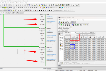
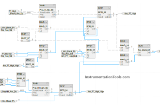
Design an efficient PLC ladder logic program that samples analog input (I:1.0) at the rate of 2Hz and outputs the average value to analog output O:1.0 once every two seconds.

PLC Analog Input Sampling Ladder Logic

PLC Analog Input Sampling

You can share the detailed explanation of above PLC ladder logic with comments section.

Author: Dr. D. J. Jackson

If you liked this article, then please subscribe to our YouTube Channel for PLC and SCADA video tutorials.

You can also follow us on Facebook and Twitter to receive daily updates.

Read Next:

  • DCS and PLC Flow Diagram
  • Logic Gates and Truth tables
  • Siemens PLC Maths Instructions
  • Two out of Three Logic Analogy
  • Motor Speed Control with PLC
Don't Miss Our Updates
Be the first to get exclusive content straight to your email.
We promise not to spam you. You can unsubscribe at any time.
Invalid email address
You've successfully subscribed !

Continue Reading

Label the Electrical Circuit Schematic
PLC Program Example on Multiple LEDs using Set Coil
SCADA System Vulnerabilities
Extended Timer Logic in PLC
Step by Step Guidelines for Downloading Free PLC software
Programming and Tuning PID Controller in PLC – Siemens TIA Portal
Share This Article
Facebook Whatsapp Whatsapp LinkedIn Copy Link
Share
Leave a Comment

Leave a Reply Cancel reply

Your email address will not be published. Required fields are marked *

Stay Connected

128.3kFollowersLike
69.1kFollowersFollow
210kSubscribersSubscribe
38kFollowersFollow

Categories

Explore More

Which Connection is Best for PLC? – Sinking or Sourcing
Configuration of InTouch Scada Trends
PLC Valve Control Ladder Logic Programming
PLC Example on Switch Program with Timers
Difference Between Microcontroller and PLC
Create a User-Defined Function Block in Codesys
Job Skills Required for Industrial Electrical Maintenance
PLC Program for Latching and unlatching Circuit

Keep Learning

Data Types in PLC

Data Types in PLC – Bit, Byte, Integer, Real, String

Conveyor Sorting Omron PLC Programming

CX-Programmer Products Sorting & Counting – Omron PLC

Set the S5 timer value by a memory word

Set the S5 Timer Value by a Memory Word

How to Delay a Sensor Signal in PLC?

How to Delay a Sensor Signal in PLC?

Add an alarm display to the graphics.

How to Configure an Alarm in InTouch SCADA?

Industrial Automation Projects

Evaluating Industrial Automation Projects Return on investment (ROI)

PLC Programming for Automated Curtain Control

Automatic Curtain Control – PLC Programming Solution

Electrical Circuit Breaker Quiz

100 Electrical Circuit Breaker Quiz

Learn More

Radiometric level Principle

Radiometric level measurement Working Principle

Dip Tube Type Level System

Questions on Dip Tube Type Level System

Instrumentation Bulk Material

Instrumentation Bulk Material Requirements in Oxygen Service

Electrical and Instrument Engineers Job Profile

Instrumentation and Electrical Teams Interactions (Detail Design Engineering)

Magnetic Level Gauge Float

Magnetic Level Gauge Float Design

Digital Electronics Multiple Choice Questions

Integrated Injection Logic (IIL) Objective Questions

Ccomparator in PLC Programming

Comparator in PLC Programming

Maintenance Override Switch (MOS)

What is Maintenance Override Switch (MOS) ?

Menu

  • About
  • Privacy Policy
  • Copyright

Quick Links

  • Learn PLC
  • Helping Hand
  • Part Time Job

YouTube Subscribe

Follow US
All rights reserved. Reproduction in whole or in part without written permission is prohibited.
Welcome Back!

Sign in to your account

Username or Email Address
Password

Lost your password?