PLC program for an artificial fishpond water level monitoring system explained with the ladder logic concept for beginners.
Water Level Monitoring System
Problem Description
Implement a PLC program for an artificial fishpond water level monitoring system.
Feed or drain the water of the artificial fishpond when the water level is below the normal level and activate the alarm when the water level is above or below the level.
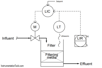
Problem Diagram

Problem Solution
This problem can be solved by using simple automation.
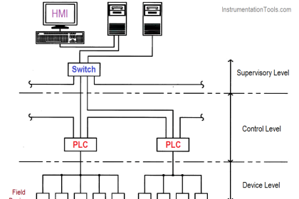
Here we considered one artificial fishpond, four level sensors and three pumps for system monitor & control.
Here we will write program that will control whole system. System will maintain normal level and it does not allow water level to go up or down to maintain the normal level.
If water level goes down from the normal level then system will feed water in the fishpond and if water level goes up from the normal level then system will drain water from the fishpond.
List of Inputs/Outputs
Inputs List
- Level Sensor, L0 : I0.0 (L0=1 when the water level is above the alarm level).
- Level Sensor, L1 : I0.1 (L1=1 when the water level is above the normal level)
- Level Sensor, L2 : I0.2 (L2=1 when the water is above the normal level)
- Level Sensor, L3 : I0.3 (L3=1 when the water is above the alarm level)
Outputs List
- Feeding pump :- Q0.0
- Drainage pump 1 :- Q0.1
- Drainage pump 2 :- Q0.2
- Alarm lamp :- Q0.3
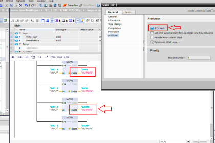
PLC Ladder Logic for artificial fishpond water level monitoring
Logic Explained
In this problem we will consider S7-300 PLC and TIA portal software for programming.
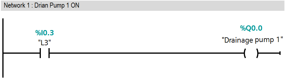
Network 1:
In this network, we have written logic for drainage pump 1 (Q0.1). When water level is above the highest level of alarm level (L3 = I0.3), at that time drainage pump 1 (Q0.1) will be ON.
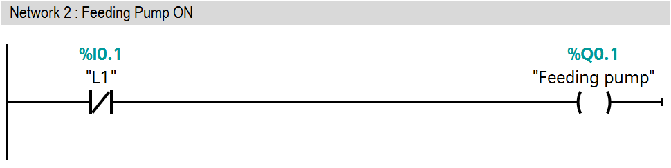
Network 2:
If water level is below the alarm level then feeding pump (Q0.0) should be start. So here we have taken NC contact of L1 (I0.1), when level is below the normal level then feeding pump (Q0.0) will ON and fill the water in the fishpond.
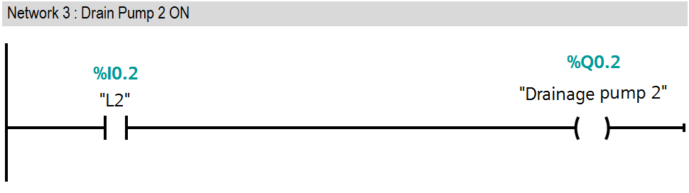
Network 3:
If water level is above the normal level then the drainage pump 2 (Q0.2) will be ON. Here water level is above than the normal level, not alarm level, so only drainage pump2 (Q0.1) will work.
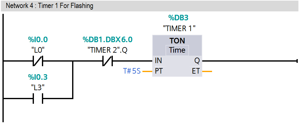
Network 4:
Here we have used two conditions in OR gate so either level is below normal level (L1 = I0.1) or above normal level (L1 = I0.1) then flashing circuit will be activated and alarm lamp (Q0.3) will be ON.
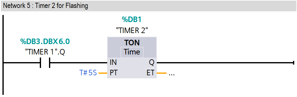
Network 5:
Timer 2 for flashing circuit.
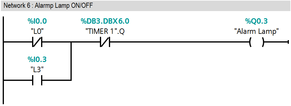
Network 6:
Here we have used two conditions in OR gate so either level is below normal level (L1=01) or above normal level then alarm lamp (Q0.3) will flash automatically on 5 second interval.
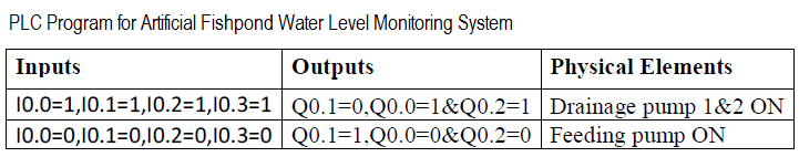
Level is above alarm level (L0=1, L1=1, L2=1, L3=1) or below alarm level (L0=0, L1=0, L2=0, L3=0) THEN alarm lamp will flash automatically on 5 seconds interval.
Level is above alarm level (L0=0, L1=0, L2=0, L3=0) then drainage pump 1&2 will start and if water level is above normal then only drainage pump 2 will start.
Note:- Above example is for explanation purpose only, not all parameters or interlocks are considered. It is not necessary to use S7-300 PLC for this simple logic, we have used this PLC for our discussion purpose.
Result
Author: Bhavesh
If you liked this article, then please subscribe to our YouTube Channel for PLC and SCADA video tutorials.
You can also follow us on Facebook and Twitter to receive daily updates.
Read Next:
- PLC Program for IEC timers
- Daily Production PLC Logic
- PLC Questions & Answers
- Automatic Bottle Rejection System
- Water filling & Discharging Process


Is Q0.1 a feed or drain pump?
feed pump-this pump used to fill any tank. AS example boiler feed pump fill water in Boiler Drum for steam making process.Another simple example is-our home roof top water vessel or tank as motor start water feed (fill) in tank.
Drain pump- this pump uses for empty any tank or vessel. Drain pump transfer water from one tank to another