Inst ToolsInst ToolsInst Tools
  • Courses
  • Automation
    • PLC
    • Control System
    • Safety System
    • Communication
    • Fire & Gas System
  • Instrumentation
    • Design
    • Pressure
    • Temperature
    • Flow
    • Level
    • Vibration
    • Analyzer
    • Control Valve
    • Switch
    • Calibration
    • Erection & Commissioning
  • Interview
    • Instrumentation
    • Electrical
    • Electronics
    • Practical
  • Q&A
    • Instrumentation
    • Control System
    • Electrical
    • Electronics
    • Analog Electronics
    • Digital Electronics
    • Power Electronics
    • Microprocessor
  • Request
Search
  • Books
  • Software
  • Projects
  • Process
  • Tools
  • Basics
  • Formula
  • Power Plant
  • Root Cause Analysis
  • Electrical Basics
  • Animation
  • Standards
  • 4-20 mA Course
  • Siemens PLC Course
Reading: ElectroMechanical Level Measurement Working Principle
Share
Notification Show More
Font ResizerAa
Inst ToolsInst Tools
Font ResizerAa
  • Courses
  • Design
  • PLC
  • Interview
  • Control System
Search
  • Courses
  • Automation
    • PLC
    • Control System
    • Safety System
    • Communication
    • Fire & Gas System
  • Instrumentation
    • Design
    • Pressure
    • Temperature
    • Flow
    • Level
    • Vibration
    • Analyzer
    • Control Valve
    • Switch
    • Calibration
    • Erection & Commissioning
  • Interview
    • Instrumentation
    • Electrical
    • Electronics
    • Practical
  • Q&A
    • Instrumentation
    • Control System
    • Electrical
    • Electronics
    • Analog Electronics
    • Digital Electronics
    • Power Electronics
    • Microprocessor
  • Request
Follow US
All rights reserved. Reproduction in whole or in part without written permission is prohibited.
Inst Tools > Blog > Level Measurement > ElectroMechanical Level Measurement Working Principle

ElectroMechanical Level Measurement Working Principle

Last updated: May 28, 2019 3:35 pm
Editorial Staff
Level Measurement
3 Comments
Share
2 Min Read
SHARE

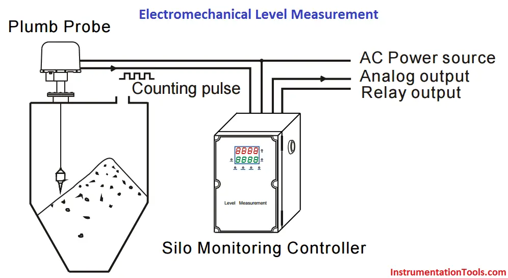
Electromechanical level Measurement Principle

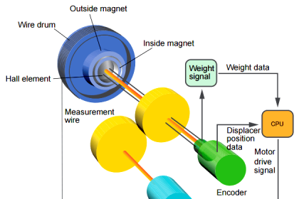
A sensing weight is let down on a measuring tape via a counter wheel. The tensile force of the weight is reduced as it hits the product surface. This is recognized, the direction of rotation of the motor reversed and the tape rewound.

As the sensing weight moves downwards, the revolutions of the wheel are counted using a non-contact method. Every count pulse corresponds to a defined length.

The level is obtained by subtracting this length from the overall length (tank height).

electromechanical-level-measurement-working-principle

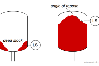
Measurement in bulk solids

Old seafarers used a weight on a rope to test the depth to the bottom of the sea. In industrial level measurement, the basic idea of sounding is still utilized in the electromechanical level system.

Where other measurement methods are limited, applications involving bulk solids predominantly use electromechanical level measurements.

Applications:

  • The result of measurement is not affected by environmental factors as sound waves, dust, static electricity, humidity and dielectric etc. Can be widely applied for applications in mining, cement, petrochemical, feeding and power plants.
  • Suitable for different variety of materials as powder, pellet, liquid, and also good for open tanks or sealed tank with no inner pressure inside.
  • Working perfectly with software of material management system, accurately monitoring and managing the level of materials inside the tank.
  • Safe measurement in extremely dusty environments
  • Robust system with high tensile force prevents breakdown due to an immersed weight
Don't Miss Our Updates
Be the first to get exclusive content straight to your email.
We promise not to spam you. You can unsubscribe at any time.
Invalid email address
You've successfully subscribed !

Continue Reading

Contact Type Guided Wave Radar Level Transmitter Working Principle
Boiler Three Element Controller Philosophy
Nuclear Level Detectors Cascade or Master/Slave concept
What is a Bridle?
Differential Pressure (DP) Level transmitter Installed Above Tapping Point
Non Contacting Radar Level Transmitter Animation
Share This Article
Facebook Whatsapp Whatsapp LinkedIn Copy Link
Share
3 Comments
  • Mineshkumar says:
    December 6, 2016 at 6:12 am

    1-What is live zero n dead zero?
    2- And what is the out put of flame detector?
    3- IP -42, IP-62 what is it and where is the use?
    4-what is the use of relay?

    Reply
    • S Bharadwaj Reddy says:
      December 6, 2016 at 6:20 am

      Hello Minesh, Plz search the website & Forum before posting your queries. I hope all answers available. Also i request you to post your further queries in our ” Forum “. You can find the forum link from the above menu. If you dont get the answers then post your questions in the forum. Thanks

      Reply
    • Chandan Ojha says:
      March 26, 2023 at 11:35 am

      In Case of 4-20 mA, and 0-20 mA, we calls 4 mA is live Zero, and 0 mA for 0-20 mA is dead zero, but in both case 0-4 mA Instrument will be at 0% Position only.
      For Flp detactor Output will be mV and that mV Conver through amplifiers signal conversion it’s convert to 4-20 mA if the mounted in field for more Automation and electrical information you can visit us on http://www.itsoji.com

      Reply

Leave a Reply Cancel reply

Your email address will not be published. Required fields are marked *

Stay Connected

128.3kFollowersLike
69.1kFollowersFollow
210kSubscribersSubscribe
38kFollowersFollow

Categories

Explore More

Differential Pressure (DP) Level transmitter Installed Below Tapping Point
Open Tank DP Level Transmitter Calibration
Magnetic Level Gauge Float Design
Float Level Measurement
How Buoyant Force instruments Works ?
Inductively Coupled Wire Guided Float Detectors
RF Level Switches Working Principle
Questions on Level Switches

Keep Learning

Tilt Level Switch Working Animation

Closed-tank-DP-Level-Transmitter-with-wet-leg-elevation-zero-direct-mount-Calibration

Closed tank DP Level Transmitter with wet leg elevation zero direct mount Calibration

Optical Level Switch Principle

Optical Level Switch Working Principle

Why Measure Level

Changing Process Medium Density has no influence on Level Indication (Full Absorption)

Nuclear Interface Level Measurement Principle, Limitations, Installation and Calibration

Surface Detector Level Measurement System

Surface Detector Level Gauges (Plumb-bob)

Level Sensors MCQ

Level Sensors MCQ – Industrial Instrumentation

magnetic-level-gauge-principle

Magnetic Level Gauge Working Principle Animation

Learn More

Electric Circuits Objective Questions

Electric Circuits Objective Questions – Set 13

illumination Multiple Choice Questions and Answers

illumination Multiple Choice Questions and Answers (MCQ)

Difference Between Normal Counters and Fast Counters - PLC Basics

Difference Between Normal Counters and Fast Counters – Learn PLC

Maintenance Override Switch (MOS)

What is Maintenance Override Switch (MOS) ?

Fire and Gas (F&G) Mapping: Methodology, Performance Targets, Acceptance Criteria

PID-Controller-Simulator-graph

PID Controller Tunning Parameters Simulator

Automated Test Bench - Complex PLC Programming Examples

Automated Test Bench – Complex PLC Programming Examples

Coriolis Mass Flow meter as a Multi Variable Transmitter - 1

Coriolis Mass Flow Meter as a Multi-Variable Transmitter

Menu

  • About
  • Privacy Policy
  • Copyright

Quick Links

  • Learn PLC
  • Helping Hand
  • Part Time Job

YouTube Subscribe

Follow US
All rights reserved. Reproduction in whole or in part without written permission is prohibited.
Welcome Back!

Sign in to your account

Username or Email Address
Password

Lost your password?