Inst ToolsInst ToolsInst Tools
  • Courses
  • Automation
    • PLC
    • Control System
    • Safety System
    • Communication
    • Fire & Gas System
  • Instrumentation
    • Design
    • Pressure
    • Temperature
    • Flow
    • Level
    • Vibration
    • Analyzer
    • Control Valve
    • Switch
    • Calibration
    • Erection & Commissioning
  • Interview
    • Instrumentation
    • Electrical
    • Electronics
    • Practical
  • Q&A
    • Instrumentation
    • Control System
    • Electrical
    • Electronics
    • Analog Electronics
    • Digital Electronics
    • Power Electronics
    • Microprocessor
  • Request
Search
  • Books
  • Software
  • Projects
  • Process
  • Tools
  • Basics
  • Formula
  • Power Plant
  • Root Cause Analysis
  • Electrical Basics
  • Animation
  • Standards
  • 4-20 mA Course
  • Siemens PLC Course
Reading: Block Diagram
Share
Notification Show More
Font ResizerAa
Inst ToolsInst Tools
Font ResizerAa
  • Courses
  • Design
  • PLC
  • Interview
  • Control System
Search
  • Courses
  • Automation
    • PLC
    • Control System
    • Safety System
    • Communication
    • Fire & Gas System
  • Instrumentation
    • Design
    • Pressure
    • Temperature
    • Flow
    • Level
    • Vibration
    • Analyzer
    • Control Valve
    • Switch
    • Calibration
    • Erection & Commissioning
  • Interview
    • Instrumentation
    • Electrical
    • Electronics
    • Practical
  • Q&A
    • Instrumentation
    • Control System
    • Electrical
    • Electronics
    • Analog Electronics
    • Digital Electronics
    • Power Electronics
    • Microprocessor
  • Request
Follow US
All rights reserved. Reproduction in whole or in part without written permission is prohibited.
Inst Tools > Blog > Electrical Theory > Block Diagram

Block Diagram

Last updated: July 23, 2018 10:12 am
Editorial Staff
Electrical Theory
No Comments
Share
1 Min Read
SHARE

A block diagram is used to show the relationship between component groups, or stages in a circuit. In block form, it shows the path through a circuit from input to output (Figure 11).

The blocks are drawn in the form of squares or rectangles connected by single lines with arrowheads at the terminal end, showing the direction of the signal path from input to output. Normally, the necessary information to describe the stages of components is contained in the blocks.

Block Diagram

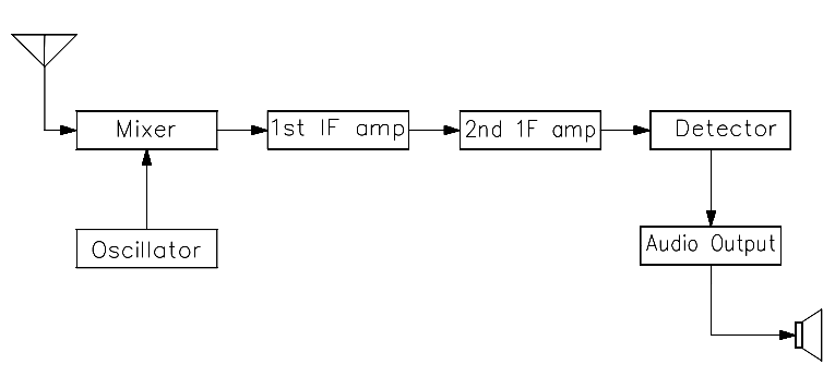
Figure 11 Block Diagram

Don't Miss Our Updates
Be the first to get exclusive content straight to your email.
We promise not to spam you. You can unsubscribe at any time.
Invalid email address
You've successfully subscribed !

Continue Reading

Conductor, Insulator, Resistor and Current Flow
What is Electricity ?
Batteries
Inductance and Inductive Reactance
Transformer Impedance Ratio
Unbalanced 3 Phase Loads
Share This Article
Facebook Whatsapp Whatsapp LinkedIn Copy Link
Share
Leave a Comment

Leave a Reply Cancel reply

Your email address will not be published. Required fields are marked *

Stay Connected

128.3kFollowersLike
69.1kFollowersFollow
210kSubscribersSubscribe
38kFollowersFollow

Categories

Explore More

Losses in AC Generator
Resistivity
DC Motor Connections
Ohm Meter
Electrical Wiring Terminology
DC Circuit Analysis Loop Equations
Calculate Power in Parallel RC Circuit
Battery Terminology

Keep Learning

Parallel Circuit

Parallel Circuit

Measuring Circuit Voltage

Voltmeters

Megger Circuit Diagram

Multimeter & Megger Principle

Core-Type Transformer

Transformer Turns Ratio

How to Measure Specific Gravity of Battery

How to Measure Specific Gravity of Battery

Auto Transformer Schematic

Classification of Transformers

Armature Current in a DC Motor

DC Motor Torque

Capacitors Connected in Parallel

Series and Parallel Capacitors

Learn More

Digital Electronics Multiple Choice Questions

Counter Implementation Objective Questions

VFD Block Diagram

What is a VFD? – Theory, Advantages, Disadvantages

Power Electronics Objective Questions

Type D Chopper Objective Questions

Rupture Disc

Working of Rupture Disk

Feedback Characteristics of Control Systems

Feedback and Non-feedback Systems Objective Questions

Acceptable Earth Resistance Values

Acceptable Earth Resistance Values

FPGA vs. CPLD - What are the differences between them

FPGA vs. CPLD – What are the differences between them

SMART Control Valve Positioner

Electronic Valve positioners

Menu

  • About
  • Privacy Policy
  • Copyright

Quick Links

  • Learn PLC
  • Helping Hand
  • Part Time Job

YouTube Subscribe

Follow US
All rights reserved. Reproduction in whole or in part without written permission is prohibited.
Welcome Back!

Sign in to your account

Username or Email Address
Password

Lost your password?