How to create an instrumentation loop drawing, say for instrument air vessel?
Contents
Piping and Instrumentation (P&ID) diagram shows the several instrumentation loops connected with particular equipment.
P&ID shows the signal path of instruments and gives an overall picture of the connected loops in the system, whereas Instrument loop diagram gives a clear idea of the instrument connected with the system.
How-to Create Instrument Loop Diagram
 It is used in checking for correct installation and connection when tested during pre-commissioning and commissioning stages, useful while troubleshooting during operation.
- Instrument loop diagram (ILD) represents a connection from the field instrument to Control Room. (vice versa)
- Instrument loop diagram is divided into two basic sections. One is the field side and other is Control Room side. (vice versa)
- Fieldside is again divided into field area and Junction box.
- Control Room side is divided into marshalling cabinet rear, Marshalling Cabinet Front.
The following data is required before starting drawing on paper for a loop diagram
- Tag No of the instrument, JB Number, Terminal block and its termination number, Marshalling cabinet and Termination details. System card and I/O details.
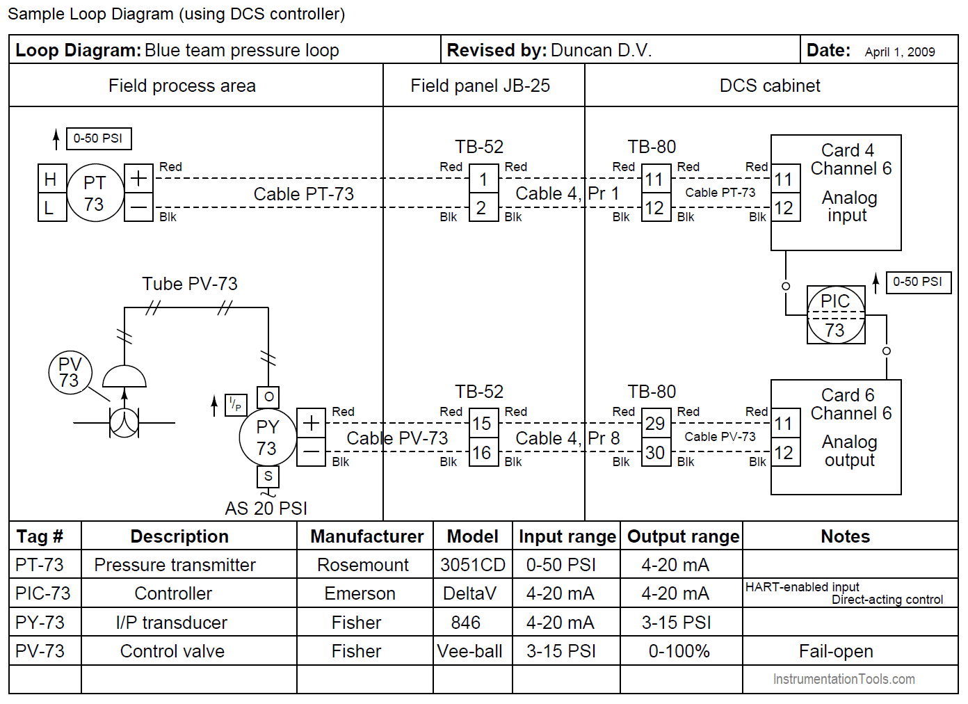
Sample Instrumentation Loop Drawing (ILD)

- Pressure transmitter PIT-01 mounted field-side it is connected by a single pair cable with red and black cable with red as (+) as 1 black (-) as 2.
- The cable connecting to junction box Tagged (JBA-01) is a single pair. Terminating in JB terminal block (at TB15, TB-16). The termination is square-shaped cable connects at IN and OUT.
- Cable from JB is terminating in Marshalling cabinet (MXA-01) number and Terminal Block number (terminal number TB15, TB16).
- Instrument sleeve is grounded at marshalling cabinet only, need not at an instrument or at junction box.
- Cable from Marshalling cabinet is connected to System I/O card.
- On the bottom right below, the details of the organization name, drawn by, verified by, approved by can be seen.
Example Loop Diagram
Read Next:
- Instrumentation Functional diagram
- Transmitter Calibration Procedure
- Process Flow Diagram (PFD)
- Single Line Diagram (SLD)
- Setpoints and Alarms in Control System


Excellent Information, Thanks very much!!
Instrument sleeve is grounded at marshalling cabinet only, need not at instrument or at junction box.
Please may I know the reason
Hi,
Cable Screen not Grounded at instrument field device? Check Here
Instruments are only grounded in one location, usually at the source or marshalling cabinet, to prevent ground loops. A ground loop is caused by a dissimilar voltage reference (earth or ground) at either end of the loop and would cause a tiny current to flow due to the differential.
Hi sir,
can i know, how Instrument Air Receiver controlled by PCV-01 on PT-01, can u explain.
your website is nice
it is my pleasure to send me any news
best regards
Instrumentation consultants Engineer
Ahmad Al Dahoul