Inst ToolsInst ToolsInst Tools
  • Courses
  • Automation
    • PLC
    • Control System
    • Safety System
    • Communication
    • Fire & Gas System
  • Instrumentation
    • Design
    • Pressure
    • Temperature
    • Flow
    • Level
    • Vibration
    • Analyzer
    • Control Valve
    • Switch
    • Calibration
    • Erection & Commissioning
  • Interview
    • Instrumentation
    • Electrical
    • Electronics
    • Practical
  • Q&A
    • Instrumentation
    • Control System
    • Electrical
    • Electronics
    • Analog Electronics
    • Digital Electronics
    • Power Electronics
    • Microprocessor
  • Request
Search
  • Books
  • Software
  • Projects
  • Process
  • Tools
  • Basics
  • Formula
  • Power Plant
  • Root Cause Analysis
  • Electrical Basics
  • Animation
  • Standards
  • 4-20 mA Course
  • Siemens PLC Course
Reading: What is Ball Valve ?
Share
Notification Show More
Font ResizerAa
Inst ToolsInst Tools
Font ResizerAa
  • Courses
  • Design
  • PLC
  • Interview
  • Control System
Search
  • Courses
  • Automation
    • PLC
    • Control System
    • Safety System
    • Communication
    • Fire & Gas System
  • Instrumentation
    • Design
    • Pressure
    • Temperature
    • Flow
    • Level
    • Vibration
    • Analyzer
    • Control Valve
    • Switch
    • Calibration
    • Erection & Commissioning
  • Interview
    • Instrumentation
    • Electrical
    • Electronics
    • Practical
  • Q&A
    • Instrumentation
    • Control System
    • Electrical
    • Electronics
    • Analog Electronics
    • Digital Electronics
    • Power Electronics
    • Microprocessor
  • Request
Follow US
All rights reserved. Reproduction in whole or in part without written permission is prohibited.
Inst Tools > Blog > Control Valves > What is Ball Valve ?

What is Ball Valve ?

Last updated: March 21, 2019 3:42 pm
Editorial Staff
Control Valves
No Comments
Share
5 Min Read
SHARE

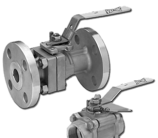
A ball valve is a rotational motion valve that uses a ball-shaped disk to stop or start fluid flow.

Contents
What is Ball Valve ?AdvantagesDisadvantagesPort PatternsValve MaterialsBall Valve Stem DesignBall Valve Bonnet DesignBall Valve Position

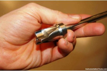
The ball, shown in Below Figure, performs the same function as the disk in the globe valve.

When the valve handle is turned to open the valve, the ball rotates to a point where the hole through the ball is in line with the valve body inlet and outlet. When the valve is shut, the ball is rotated so that the hole is perpendicular to the flow openings of the valve body and the flow is stopped.

What is Ball Valve ?

Most ball valve actuators are of the quick-acting type, which require a 90° turn of the valve handle to operate the valve. Other ball valve actuators are planetary gear-operated. This type of gearing allows the use of a relatively small handwheel and operating force to operate a fairly large valve.

Some ball valves have been developed with a spherical surface coated plug that is off to one side in the open position and rotates into the flow passage until it blocks the flow-path completely.

Seating is accomplished by the eccentric movement of the plug. The valve requires no lubrication and can be used for throttling service.

Ball Valve Parts

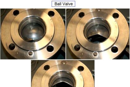
Ball Valve Positions : Open to Close

Ball Valve Positions

Figure : Typical Ball Valve

Advantages

A ball valve is generally the least expensive of any valve configuration and has low maintenance costs.

In addition to quick, quarter turn on-off operation, ball valves are compact, require no lubrication, and give tight sealing with low torque.

Disadvantages

Conventional ball valves have relatively poor throttling characteristics.

In a throttling position, the partially exposed seat rapidly erodes because of the impingement of high velocity flow.

Port Patterns

Ball valves are available in the venturi, reduced, and full port pattern. The full port pattern has a ball with a bore equal to the inside diameter of the pipe.

Valve Materials

Balls are usually metallic in metallic bodies with trim (seats) produced from elastomeric (elastic materials resembling rubber) materials. Plastic construction is also available.

The resilient seats for ball valves are made from various elastomeric material. The most common seat materials are teflon (TFE), filled TFE, Nylon, Buna-N, Neoprene, and combinations of these materials.

Because of the elastomeric materials, these valves cannot be used at elevated temperatures. Care must be used in the selection of the seat material to ensure that it is compatible with the materials being handled by the valve.

Ball Valve Stem Design

The stem in a ball valve is not fastened to the ball. It normally has a rectangular portion at the ball end which fits into a slot cut into the ball. The enlargement permits rotation of the ball as the stem is turned.

Ball Valve Bonnet Design

A bonnet cap fastens to the body, which holds the stem assembly and ball in place. Adjustment of the bonnet cap permits compression of the packing, which supplies the stem seal.

Packing for ball valve stems is usually in the configuration of die-formed packing rings normally of TFE, TFE-filled, or TFE-impregnated material. Some ball valve stems are sealed by means of O-rings rather than packing.

Ball Valve Position

Some ball valves are equipped with stops that permit only 90° rotation. Others do not have stops and may be rotated 360°. With or without stops, a 90° rotation is all that is required for closing or opening a ball valve.

The handle indicates valve ball position. When the handle lies along the axis of the valve, the valve is open. When the handle lies 90° across the axis of the valve, the valve is closed.

Some ball valve stems have a groove cut in the top face of the stem that shows the flowpath through the ball. Observation of the groove position indicates the position of the port through the ball. This feature is particularly advantageous on multiport ball valves.

Articles You May Like :

Classification of Control Valves

Testing of Valve Positioner

Control Valve Interview Questions

Fundamentals of valves

What is Flapper Nozzle System ?

Don't Miss Our Updates
Be the first to get exclusive content straight to your email.
We promise not to spam you. You can unsubscribe at any time.
Invalid email address
You've successfully subscribed !

Continue Reading

Difference between Butterfly Valves and Ball Valves
Pneumatic Control Valve Actuators
Cavitation Test Setup
Quick Exhaust and Air Operated Valves in Instrumentation Circuit
Control Valve Stroke Test Procedure
Metal Seated Valves and Soft Seated Valves : Differences
Share This Article
Facebook Whatsapp Whatsapp LinkedIn Copy Link
Share
Leave a Comment

Leave a Reply Cancel reply

Your email address will not be published. Required fields are marked *

Stay Connected

128.3kFollowersLike
69.1kFollowersFollow
210kSubscribersSubscribe
38kFollowersFollow

Categories

Explore More

Difference between PCV and PRV
What is Gate Valve ?
What is a Hydraulic Valve? and their Types
Spring and Diaphragm Pneumatic Actuators
DIN Valve Connectors – Definition, Types
Rotary Stem Valves
SIS Emergency Block Valves (EBV)
Instrumentation Inspection Report

Keep Learning

Difference-between-pneumatic-electric-hydraulic-actuators

Difference between Pneumatic, Electrical & Hydraulic Actuators

Globe Valve Disk and Stem Connections

Globe Valve Seat and Disk

Y Body Globe Valve

Globe Valve Body Design

Control Valves Pre-Commissioning Checklist

Control Valves Pre-Commissioning Checklist

Motor Operated Valve Problems and Troubleshooting

Motor Operated Valve Problems and Troubleshooting

self-operated pressure regulating valve

Working Principle of Self Operated Valves

Valves Legend P&ID

Comparison of Gate Valves and Globe Valves

Types of Pneumatic Valves

Types of Pneumatic Valves : Poppet & Spool

Learn More

Digital Electronics Multiple Choice Questions

Random Access Memory Objective Questions – Part 2

Range Finders

Range Finders – Ultrasonic, Light, & Global Positioning Systems

Thermostatic valves Principle

Thermostatic Valves Working Principle

Run 4 Motors Sequentially from Same Push button PLC Program

Run 4 Motors Sequentially from Same Push button PLC Program

PLC Timer Programming Examples – TON, TOF, TP and TONR

pilot operated relief valves

Pilot-operated Relief Valve Principle

Flange Types and Definitions

Flange Types and Definitions

How to Setup a Smart Transmitter Using a HART Communicator

How to Configure a Smart Transmitter Using a HART Communicator?

Menu

  • About
  • Privacy Policy
  • Copyright

Quick Links

  • Learn PLC
  • Helping Hand
  • Part Time Job

YouTube Subscribe

Follow US
All rights reserved. Reproduction in whole or in part without written permission is prohibited.
Welcome Back!

Sign in to your account

Username or Email Address
Password

Lost your password?