Let’s study the working of converter instruction in Siemens PLC programming using different ladder logics and programs.
Converter Instruction in PLC

Block Description
Round to double integer:
It reads the input floating point value and converts it to double integer and round to nearest integer. The result is output by the parameter OUT.

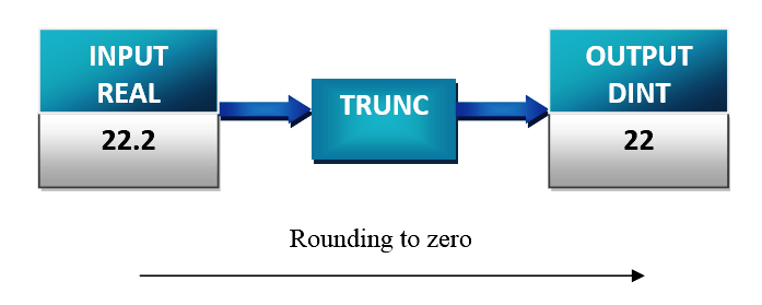
Truncate double integer part:
It reads the input floating point value and converts it to double integer and round to zero mode. The result is output by the parameter OUT.
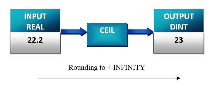
Ceiling:
It reads the input floating point value and converts it to double integer. The result is the lowest integer which is greater than the floating point number i.e Round to + infinity mode. The result is output by the parameter OUT.
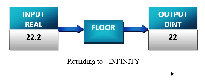
Floor:
It reads the input floating point value and converts it to double integer. The result is the greatest integer component which is greater than the floating point number i.e Round to -infinity mode. The result is output by the parameter OUT.
Ladder Logic

Ladder Description:
Network 1:
If I0.0 is pressed, value in MD0 (99.78) is read as a floating point number and converted to the closest double integer(100). The result of round to integer is stored in MD4(100).
Network 2:
If I0.0 is pressed, value in MD0 (99.78) is read as a floating point number and converted to the double integer. The integer part of the floating point number is the result. The result is stored in MD12 (99).
Network 3:
If I0.0 is pressed, value in MD0 (99.78) is read as a floating point number and converted to the double integer by round function . The result is stored in MD12 (100).
Network 4:
If I0.0 is pressed, value in MD0 (99.78)is read as a floating point number and converted to the double integer by the round to – infinity mode. The result is stored in MD16(99).
Note: For positive numbers, trunc and floor give the same result. But for negative numbers, floor rounds down and trunc rounds up. This is because trunc always rounds toward 0.
Author: Hema Sundaresan
If you liked this article, then please subscribe to our YouTube Channel for PLC and SCADA video tutorials.
You can also follow us on Facebook and Twitter to receive daily updates.
Read Next:
- JUMP Instruction in PLC Programs
- Master Control Reset (MCR) in PLC
- One-Shot Rising & Falling Instructions
- Sequence and Logic Control in PLC
- Scaling with Parameters Instruction
- What is DCS and ESD Systems?