DC generators are widely used to produce a DC voltage. The amount of voltage produced depends on a variety of factors.
Voltage Production
For DC Circuits there are three conditions necessary to induce a voltage into a conductor.
They are :
- A magnetic field
- A conductor
- Relative motion between the two
A DC generator provides these three conditions to produce a DC voltage output.
Theory of Operation
A basic DC generator has four basic parts:
- a magnetic field;
- a single conductor, or loop;
- a commutator; and
- brushes
The magnetic field may be supplied by either a permanent magnet or an electromagnet. For now, we will use a permanent magnet to describe a basic DC generator (Figure 3).
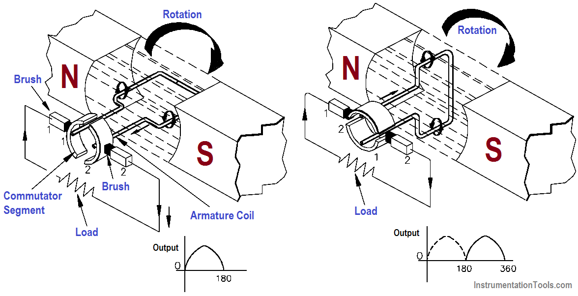
Figure 3 : Basic Operation of a DC Generator
A single conductor, shaped in the form of a loop, is positioned between the magnetic poles. As long as the loop is stationary, the magnetic field has no effect (no relative motion). If we rotate the loop, the loop cuts through the magnetic field, and an EMF (voltage) is induced into the loop.
When we have relative motion between a magnetic field and a conductor in that magnetic field, and the direction of rotation is such that the conductor cuts the lines of flux, an EMF is induced into the conductor. The magnitude of the induced EMF depends on the field strength and the rate at which the flux lines are cut, as given in below equation. The stronger the field or the more flux lines cut for a given period of time, the larger the induced EMF.
Eg = KΦN
where
Eg = generated voltage
K = fixed constant
Φ = magnetic flux strength
N = speed in RPM
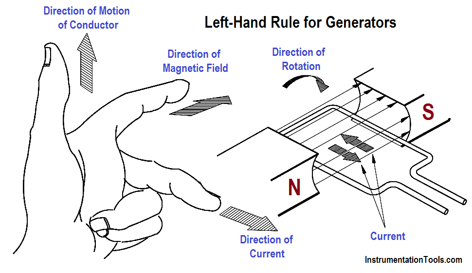
The direction of the induced current flow can be determined using the “left-hand rule” for generators. This rule states that if you point the index finger of your left hand in the direction of the magnetic field (from North to South) and point the thumb in the direction of motion of the conductor, the middle finger will point in the direction of current flow (Figure 4).
In the generator shown in Figure 4, for example, the conductor closest to the N pole is traveling upward across the field; therefore, the current flow is to the right, lower corner. Applying the left-hand rule to both sides of the loop will show that current flows in a counter-clockwise direction in the loop.
Commutator Action
The commutator converts the AC voltage generated in the rotating loop into a DC voltage. It also serves as a means of connecting the brushes to the rotating loop. The purpose of the brushes is to connect the generated voltage to an external circuit. In order to do this, each brush must make contact with one of the ends of the loop. Since the loop or armature rotates, a direct connection is impractical. Instead, the brushes are connected to the ends of the loop through the commutator.
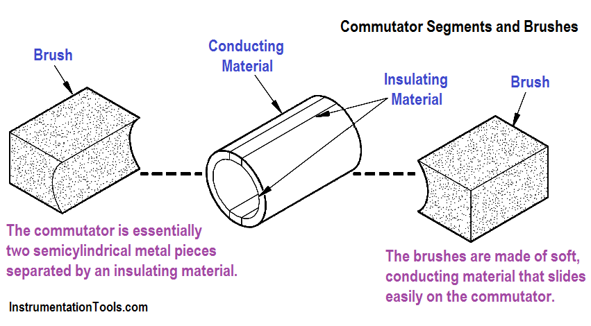
Figure 5 : Commutator Segments and Brushes
In a simple one-loop generator, the commutator is made up of two semicylindrical pieces of a smooth conducting material, usually copper, separated by an insulating material, as shown in Figure 5. Each half of the commutator segments is permanently attached to one end of the rotating loop, and the commutator rotates with the loop. The brushes, usually made of carbon, rest against the commutator and slide along the commutator as it rotates. This is the means by which the brushes make contact with each end of the loop.
Each brush slides along one half of the commutator and then along the other half. The brushes are positioned on opposite sides of the commutator; they will pass from one commutator half to the other at the instant the loop reaches the point of rotation, at which point the voltage that was induced reverses the polarity.
Every time the ends of the loop reverse polarity, the brushes switch from one commutator segment to the next. This means that one brush is always positive with respect to another. The voltage between the brushes fluctuates in amplitude (size or magnitude) between zero and some maximum value, but is always of the same polarity (Figure 6). In this manner, commutation is accomplished in a DC generator.
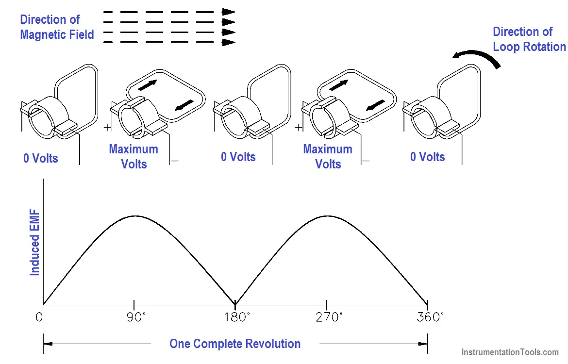
Figure 6 : Commutation in a DC Generator
One important point to note is that, as the brushes pass from one segment to the other, there is an instant when the brushes contact both segments at the same time. The induced voltage at this point is zero. If the induced voltage at this point were not zero, extremely high currents would be produced due to the brushes shorting the ends of the loop together. The point at which the brushes contact both commutator segments, when the induced voltage is zero, is called the “neutral plane.”
Field Excitation
The magnetic fields in DC generators are most commonly provided by electromagnets. A current must flow through the electromagnet conductors to produce a magnetic field. In order for a DC generator to operate properly, the magnetic field must always be in the same direction.
Therefore, the current through the field winding must be direct current. This current is known as the field excitation current and can be supplied to the field winding in one of two ways. It can come from a separate DC source external to the generator (e.g., a separately excited generator) or it can come directly from the output of the generator, in which case it is called a self-excited generator.
In a self-excited generator, the field winding is connected directly to the generator output. The field may be connected in series with the output, in parallel with the output, or a combination of the two.
Separate excitation requires an external source, such as a battery or another DC source. It is generally more expensive than a self-excited generator. Separately excited generators are, therefore, used only where self-excitation is not satisfactory. They would be used in cases where the generator must respond quickly to an external control source or where the generated voltage must be varied over a wide range during normal operations.
Terminal Voltage
DC generator output voltage is dependent on three factors :
- the number of conductor loops in series in the armature,
- armature speed, and
- magnetic field strength.
In order to change the generator output, one of these three factors must be varied. The number of conductors in the armature cannot be changed in a normally operating generator, and it is usually impractical to change the speed at which the armature rotates. The strength of the magnetic field, however, can be changed quite easily by varying the current through the field winding. This is the most widely used method for regulating the output voltage of a DC generator (Figure 7).
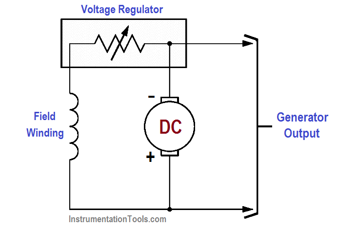
Figure 7 : Varying Generator Terminal Voltage
DC Generator Ratings
A DC generator contains four ratings.
Voltage: Voltage rating of a machine is based on the insulation type and design of the machine.
Current: The current rating is based on the size of the conductor and the amount of heat that can be dissipated in the generator.
Power: The power rating is based on the mechanical limitations of the device that is used to turn the generator and on the thermal limits of conductors, bearings, and other components of the generator.
Speed: Speed rating, at the upper limit, is determined by the speed at which mechanical damage is done to the machine. The lower speed rating is based on the limit for field current (as speed increases, a higher field current is necessary to produce the same voltage).