Inductors will store energy in the form of a magnetic field. Circuits containing inductors will behave differently from a simple resistance circuit. In circuits with elements that store energy, it is common for current and voltage to exhibit exponential increase and decay (Figure 6).
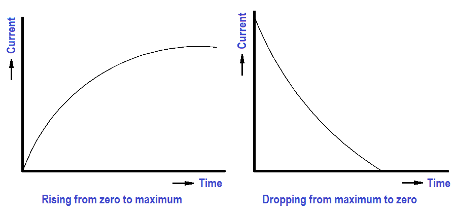
Figure 6 : DC Current Through an Inductor
The relationship between values of current reached and the time it takes to reach them is called a time constant. The time constant for an inductor is defined as the time required for the current either to increase to 63.2 percent of its maximum value or to decrease by 63.2 percent of its maximum value (Figure 7).
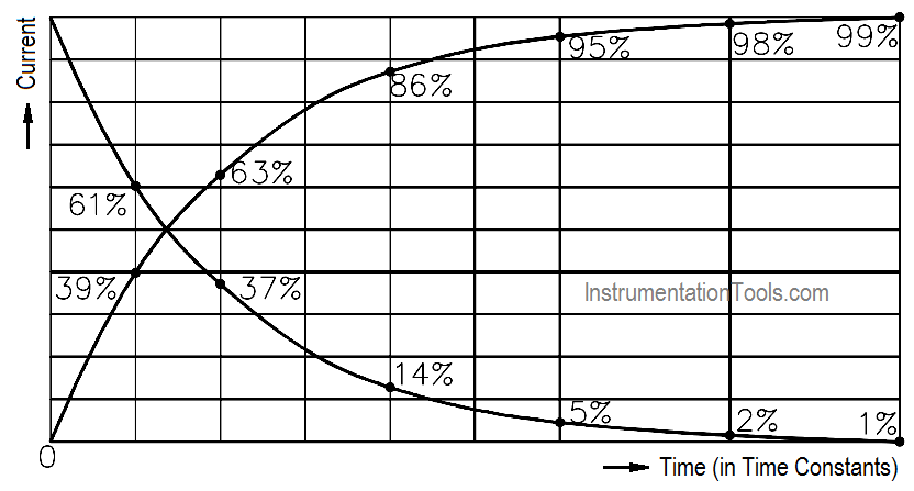
Figure 7 : Time Constant
The value of the time constant is directly proportional to the inductance and inversely proportional to the resistance. If these two values are known, the time constant can be found using below Equation.

where
TL = time constant (seconds)
L = inductance (henries)
R = resistance (ohms)
The voltage drop across an inductor is directly proportional to the product of the inductance and the time rate of change of current through the inductor, as shown in below Equation.

where
VL = voltage drop across the inductor (volts)
L = inductance (henries)
∆I/∆t = time rate of change of current (amp/sec)
After five time constants, circuit parameters normally reach their final value. Circuits that contain both inductors and resistors are called RL circuits.
The following example will illustrate how an RL circuit reacts to changes in the circuit (Figure 8).
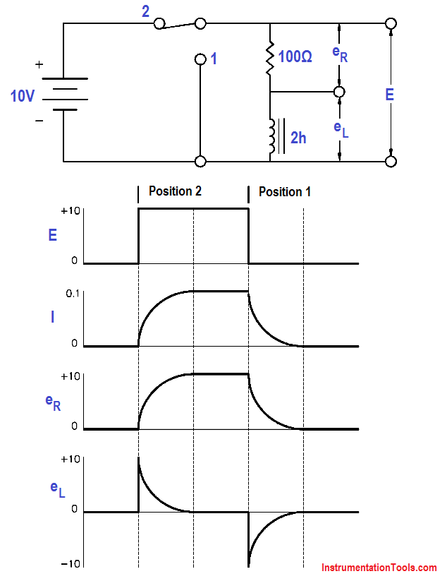
Figure 8 : Voltage Applied to an Inductor
1. Initially, the switch is in Position 1, and no current flows through the inductor.
2. When we move the switch to Position 2, the battery attempts to force a current of 10v/100Ω = 0.1A through the inductor. But as current begins to flow, the inductor generates a magnetic field. As the field increases, a counter EMF is induced that opposes the battery voltage. As a steady state is reached, the counter EMF goes to zero exponentially.
3. When the switch is returned to Position 1, the magnetic field collapses, inducing an EMF that tends to maintain current flow in the same direction through the inductor. Its polarity will be opposite to that induced when the switch was placed in Position 2.
The example that follows shows how a circuit with an inductor in parallel with a resistor reacts to changes in the circuit. Inductors have some small resistance, and this is shown schematically as a 1Ω resistor (Figure 9).
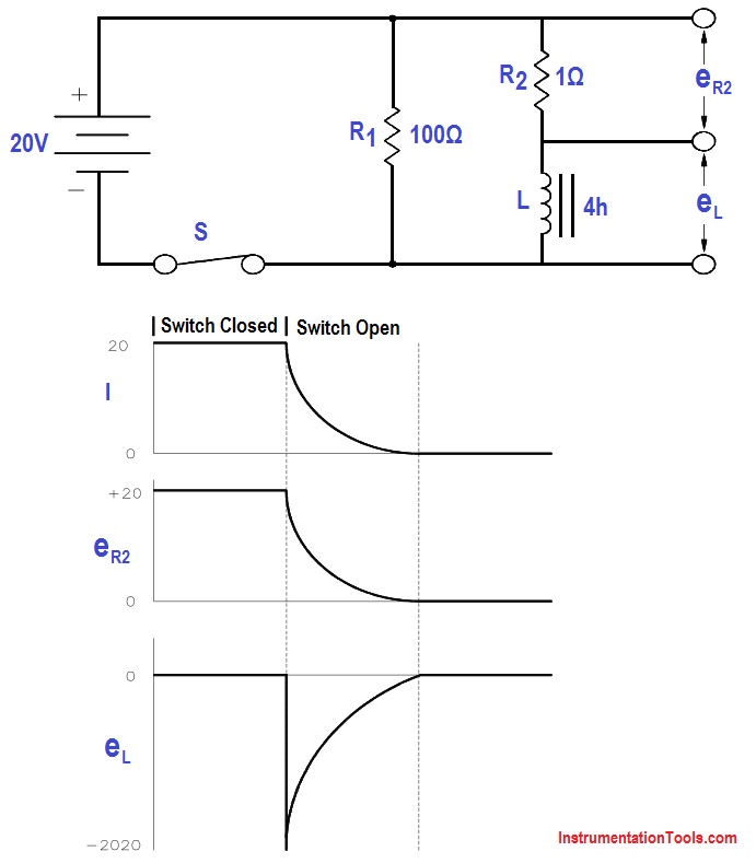
Figure 9 : Inductor and Resistor in Parallel
1. While the switch is closed, a current of 20 v/1Ω = 20 amps flows through the inductor. This causes a very large magnetic field around the inductor.
2. When we open the switch, there is no longer a current through the inductor. As the magnetic field begins to collapse, a voltage is induced in the inductor. The change in applied voltage is instantaneous; the counter EMF is of exactly the right magnitude to prevent the current from changing initially. In order to maintain the current at 20 amps flowing through the inductor, the self-induced voltage in the inductor must be enough to push 20 amps through the 101Ω of resistance. The CEMF = (101)(20) = 2020 volts.
3. With the switch open, the circuit looks like a series RL circuit without a battery. The CEMF induced falls off, as does the current, with a time constant TL of:

TL = 4h/101 Ω = 0.039 sec
