Inst ToolsInst ToolsInst Tools
  • Courses
  • Automation
    • PLC
    • Control System
    • Safety System
    • Communication
    • Fire & Gas System
  • Instrumentation
    • Design
    • Pressure
    • Temperature
    • Flow
    • Level
    • Vibration
    • Analyzer
    • Control Valve
    • Switch
    • Calibration
    • Erection & Commissioning
  • Interview
    • Instrumentation
    • Electrical
    • Electronics
    • Practical
  • Q&A
    • Instrumentation
    • Control System
    • Electrical
    • Electronics
    • Analog Electronics
    • Digital Electronics
    • Power Electronics
    • Microprocessor
  • Request
Search
  • Books
  • Software
  • Projects
  • Process
  • Tools
  • Basics
  • Formula
  • Power Plant
  • Root Cause Analysis
  • Electrical Basics
  • Animation
  • Standards
  • 4-20 mA Course
  • Siemens PLC Course
Reading: Kirchhoff’s Laws
Share
Notification Show More
Font ResizerAa
Inst ToolsInst Tools
Font ResizerAa
  • Courses
  • Design
  • PLC
  • Interview
  • Control System
Search
  • Courses
  • Automation
    • PLC
    • Control System
    • Safety System
    • Communication
    • Fire & Gas System
  • Instrumentation
    • Design
    • Pressure
    • Temperature
    • Flow
    • Level
    • Vibration
    • Analyzer
    • Control Valve
    • Switch
    • Calibration
    • Erection & Commissioning
  • Interview
    • Instrumentation
    • Electrical
    • Electronics
    • Practical
  • Q&A
    • Instrumentation
    • Control System
    • Electrical
    • Electronics
    • Analog Electronics
    • Digital Electronics
    • Power Electronics
    • Microprocessor
  • Request
Follow US
All rights reserved. Reproduction in whole or in part without written permission is prohibited.
Inst Tools > Blog > Electrical Theory > Kirchhoff’s Laws

Kirchhoff’s Laws

Last updated: July 23, 2018 4:27 pm
Editorial Staff
Electrical Theory
No Comments
Share
2 Min Read
SHARE

Kirchhoff’s two laws reveal a unique relationship between current, voltage, and resistance in electrical circuits that is vital to performing and understanding electrical circuit analysis.

Kirchhoff’s Laws

In all of the circuits examined so far, Ohm’s Law described the relationship between current, voltage, and resistance. These circuits have been relatively simple in nature. Many circuits are extremely complex and cannot be solved with Ohm’s Law. These circuits have many power sources and branches which would make the use of Ohm’s Law impractical or impossible.

Through experimentation in 1857 the German physicist Gustav Kirchhoff developed methods to solve complex circuits. Kirchhoff developed two conclusions, known today as Kirchhoff’s Laws.

Law 1:

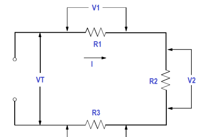
The sum of the voltage drops around a closed loop is equal to the sum of the voltage sources of that loop (Kirchhoff’s Voltage Law).

Law 2:

The current arriving at any junction point in a circuit is equal to the current leaving that junction (Kirchhoff’s Current Law).

Kirchhoff’s two laws may seem obvious based on what we already know about circuit theory. Even though they may seem very simple, they are powerful tools in solving complex and difficult circuits.

Kirchhoff’s laws can be related to conservation of energy and charge if we look at a circuit with one load and source. Since all of the power provided from the source is consumed by the load, energy and charge are conserved. Since voltage and current can be related to energy and charge, then Kirchhoff’s laws are only restating the laws governing energy and charge conservation.

The mathematics involved becomes more difficult as the circuits become more complex. Therefore, the discussion here will be limited to solving only relatively simple circuits.

Read about two laws :
  1. Kirchhoff’s Voltage Law
  2. Kirchhoff’s Current Law
Don't Miss Our Updates
Be the first to get exclusive content straight to your email.
We promise not to spam you. You can unsubscribe at any time.
Invalid email address
You've successfully subscribed !

Continue Reading

AC Motor Theory
Three Phase Transformer Connections
Parallel AC Generators
Batteries Theory
3-Wire, Three-Phase Delta Wiring System
Transformer Losses and Efficiency
Share This Article
Facebook Whatsapp Whatsapp LinkedIn Copy Link
Share
Leave a Comment

Leave a Reply Cancel reply

Your email address will not be published. Required fields are marked *

Stay Connected

128.3kFollowersLike
69.1kFollowersFollow
210kSubscribersSubscribe
38kFollowersFollow

Categories

Explore More

Magnetism
Ammeter
Electrical Wiring Terminology
AC Generator Theory
Voltage and Current Phase Relationships in an Inductive Circuit
Reading Electrical Schematics
DC Generator Internal Losses
D’Arsonval Meter Movement

Keep Learning

Voltage Drop in a Series Circuit

Series Resistance

Chemical Battery

Batteries

Ohm Meter Circuit

Ohm Meter

Inductors in parallel

Series and Parallel Inductors

Capacitors Connected in Parallel

Series and Parallel Capacitors

Basic AC Generator

AC Generator Parts

Capacitor and Symbols

Capacitance

Calculate Power in Series RC Circuit

Calculate Power in Series RC Circuit

Learn More

Applications of Synchronous Motors

Digital Electronics MCQ

Binary Coded Decimal (BCD) Objective Questions

Transducers MCQ

Transducers MCQ

Power Electronics objective questions and answers

Top 50 Power Electronics Quiz

Power Electronics Objective Questions

Thyristor Chopper Circuit Quiz

Programmable Logic Controller (PLC) Questions and Answers

Programmable Logic Controller (PLC) Questions and Answers – 1

IPSec

What is IPSec? – Internet Protocol Security

LED Stumps in Cricket

How do LED Stumps in Cricket Work?

Menu

  • About
  • Privacy Policy
  • Copyright

Quick Links

  • Learn PLC
  • Helping Hand
  • Part Time Job

YouTube Subscribe

Follow US
All rights reserved. Reproduction in whole or in part without written permission is prohibited.
Welcome Back!

Sign in to your account

Username or Email Address
Password

Lost your password?